Vectra Genisys Service Manual - DJO Global
Vectra Genisys Service Manual - DJO Global
Vectra Genisys Service Manual - DJO Global
- No tags were found...

You also want an ePaper? Increase the reach of your titles
YUMPU automatically turns print PDFs into web optimized ePapers that Google loves.
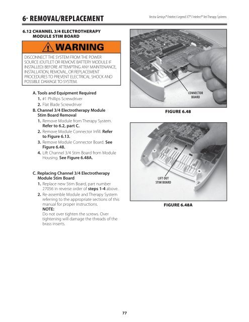
6- REMOVAL/REPLACEMENT<strong>Vectra</strong> <strong>Genisys</strong>®/Intelect Legend XT®/ Intelect® Vet Therapy Systems6.12 CHANNEL 3/4 ELECTROTHERAPYMODULE STIM BOARDDISCONNECT THE SYSTEM FROM THE POWERSOURCE (OUTLET OR REMOVE BATTERY MODULE IFINSTALLED) BEFORE ATTEMPTING ANY MAINTENANCE,INSTALLATION, REMOVAL, OR REPLACEMENTPROCEDURES TO PREVENT ELECTRICAL SHOCK ANDPOSSIBLE DAMAGE TO SYSTEM.A. Tools and Equipment Required1. #1 Phillips Screwdriver2. Flat Blade ScrewdriverB. Channel 3/4 Electrotherapy ModuleStim Board Removal1. Remove Module from Therapy System.Refer to 6.2, part C.2. Remove Module Connector Infill. Referto Figure 6.13.3. Remove Module Connector Board. SeeFigure 6.48.4. Lift Channel 3/4 Stim Board from ModuleHousing. See Figure 6.48A.FIGURE 6.48CONNECTORBOARDC. Replacing Channel 3/4 ElectrotherapyModule Stim Board1. Replace new Stim Board, part number27056 in reverse order of steps 1-4 above.2. Re-assemble Module and Therapy Systemreferring to the appropriate sections of thismanual for proper instructions.NOTE:Do not over tighten the screws. Overtightening will damage the threads of thebrass inserts.LIFT OUTSTIM BOARDFIGURE 6.48A77