Vectra Genisys Service Manual - DJO Global
Vectra Genisys Service Manual - DJO Global
Vectra Genisys Service Manual - DJO Global
- No tags were found...

You also want an ePaper? Increase the reach of your titles
YUMPU automatically turns print PDFs into web optimized ePapers that Google loves.
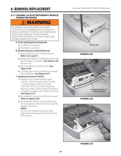
6- REMOVAL/REPLACEMENT<strong>Vectra</strong> <strong>Genisys</strong>®/Intelect Legend XT®/ Intelect® Vet Therapy Systems6.11 CHANNEL 3/4 ELECTROTHERAPY MODULECONNECTOR BOARDDISCONNECT THE SYSTEM FROM THE POWERSOURCE (OUTLET OR REMOVE BATTERY MODULE IFINSTALLED) BEFORE ATTEMPTING ANY MAINTENANCE,INSTALLATION, REMOVAL, OR REPLACEMENTPROCEDURES TO PREVENT ELECTRICAL SHOCK ANDPOSSIBLE DAMAGE TO SYSTEM.A. Tools and Equipment Required1. #1 Phillips Screwdriver2. Flat Blade ScrewdriverB. Module Connector Board Removal1. Remove Module from Therapy System.Refer to 6.2, part C.2. Release the Module Top Retaining Tabs withthe Flat Blade Screwdriver. See Figure 6.45.Remove Top.3. Remove Module Connector Infill. SeeFigure 6.46.4. Carefully pull Connector Board out towardfront of Module. See Figure 6.47.C. Replacing Connector Board1. Replace new Connector Board, partnumber 27059 in reverse order of steps1-4 above. Make Certain the words“THIS SIDE UP” on Connector Board arefacing up. Make certain Connector Board iscompletely seated in Stim Board Connector.See Figure 6.47.2. Re-install the Connector Infill and Lanyard.Refer to Figure 6.46.3. Re-assemble Therapy System referring tothe appropriate sections of this manual forproper instructions.NOTE:Do not over tighten the screws. Overtightening will damage the threads of thebrass inserts.FIGURE 6.45FIGURE 6.46RELEASE TABSLIFT CONNECTOR INFILL OUTOF MODULE HOUSINGFIGURE 6.4776