Vectra Genisys Service Manual - DJO Global
Vectra Genisys Service Manual - DJO Global
Vectra Genisys Service Manual - DJO Global
- No tags were found...

You also want an ePaper? Increase the reach of your titles
YUMPU automatically turns print PDFs into web optimized ePapers that Google loves.
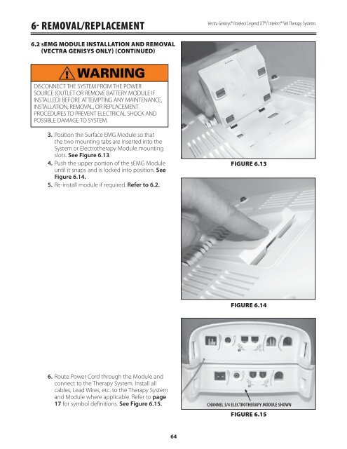
6- REMOVAL/REPLACEMENT<strong>Vectra</strong> <strong>Genisys</strong>®/Intelect Legend XT®/ Intelect® Vet Therapy Systems6.2 SEMG MODULE INSTALLATION AND REMOVAL(VECTRA GENISYS ONLY) (CONTINUED)DISCONNECT THE SYSTEM FROM THE POWERSOURCE (OUTLET OR REMOVE BATTERY MODULE IFINSTALLED) BEFORE ATTEMPTING ANY MAINTENANCE,INSTALLATION, REMOVAL, OR REPLACEMENTPROCEDURES TO PREVENT ELECTRICAL SHOCK ANDPOSSIBLE DAMAGE TO SYSTEM.3.4.5.Position the Surface EMG Module so thatthe two mounting tabs are inserted into theSystem or Electrotherapy Module mountingslots. See Figure 6.13.Push the upper portion of the sEMG Moduleuntil it snaps and is locked into position. SeeFigure 6.14.Re-install module if required. Refer to 6.2.FIGURE 6.13FIGURE 6.146.Route Power Cord through the Module andconnect to the Therapy System. Install allcables, Lead Wires, etc. to the Therapy Systemand Module where applicable. Refer to page17 for symbol definitions. See Figure 6.15.CHANNEL 3/4 ELECTROTHERAPY MODULE SHOWNFIGURE 6.1564