Vectra Genisys Service Manual - DJO Global
Vectra Genisys Service Manual - DJO Global
Vectra Genisys Service Manual - DJO Global
- No tags were found...

Create successful ePaper yourself
Turn your PDF publications into a flip-book with our unique Google optimized e-Paper software.
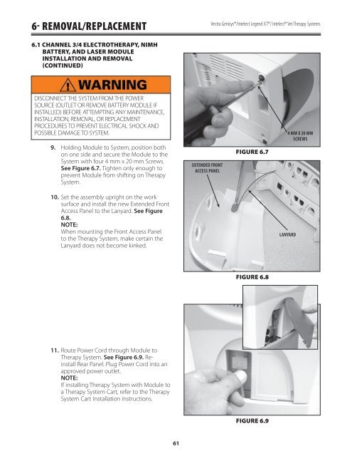
6- REMOVAL/REPLACEMENT<strong>Vectra</strong> <strong>Genisys</strong>®/Intelect Legend XT®/ Intelect® Vet Therapy Systems6.1 CHANNEL 3/4 ELECTROTHERAPY, NIMHBATTERY, AND LASER MODULEINSTALLATION AND REMOVAL(CONTINUED)DISCONNECT THE SYSTEM FROM THE POWERSOURCE (OUTLET OR REMOVE BATTERY MODULE IFINSTALLED) BEFORE ATTEMPTING ANY MAINTENANCE,INSTALLATION, REMOVAL, OR REPLACEMENTPROCEDURES TO PREVENT ELECTRICAL SHOCK ANDPOSSIBLE DAMAGE TO SYSTEM.9.Holding Module to System, position bothon one side and secure the Module to theSystem with four 4 mm x 20 mm Screws.See Figure 6.7. Tighten only enough toprevent Module from shifting on TherapySystem.EXTENDED FRONTACCESS PANELFIGURE 6.74 MM X 20 MMSCREWS10.Set the assembly upright on the worksurface and install the new Extended FrontAccess Panel to the Lanyard. See Figure6.8.NOTE:When mounting the Front Access Panelto the Therapy System, make certain theLanyard does not become kinked.LANYARDFIGURE 6.811.Route Power Cord through Module toTherapy System. See Figure 6.9. ReinstallRear Panel. Plug Power Cord into anapproved power outlet.NOTE:If installing Therapy System with Module toa Therapy System Cart, refer to the TherapySystem Cart Installation instructions.FIGURE 6.961