AlphaCom XE - Zenitel
AlphaCom XE - Zenitel
AlphaCom XE - Zenitel
- No tags were found...

Create successful ePaper yourself
Turn your PDF publications into a flip-book with our unique Google optimized e-Paper software.
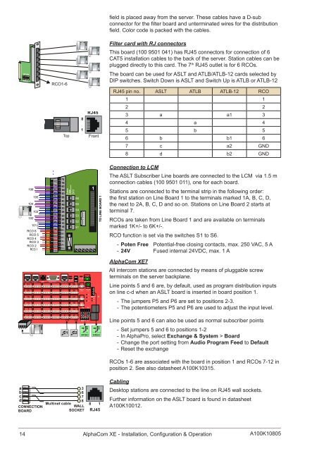
VMP-D619# *1 2 3 4 5 STENTOFON1 2 34 5 67 8 9M 0 CVINGTORAC- DC-GND GNDVMP-D619# *1 2 3 4 5 STENTOFON1 2 34 5 67 8 9M 0 CVINGTORVMP-D619# *1 2 3 4 5 STENTOFON1 2 34 5 67 8 9M 0 CVINGTORVMP-D619# *1 2 3 4 5 STENTOFON1 2 34 5 67 8 9M 0 CVINGTORVMP-D619# *1 2 3 4 5 STENTOFON1 2 34 5 67 8 9M 0 CVINGTORVMP-D619# *1 2 3 4 5 STENTOFON1 2 34 5 67 8 9M 0 CVINGTORVMP-D619# *1 2 3 4 5 STENTOFON1 2 34 5 67 8 9M 0 CVINGTORVMP-D619# *1 2 3 4 5 STENTOFON1 2 34 5 67 8 9M 0 CVINGTORRCO1-6TopRJ4581Frontfield is placed away from the server. These cables have a D-subconnector for the filter board and unterminated wires for the distributionfield. Color code is packed with the cables.Filter card with RJ connectorsThis board (100 9501 041) has RJ45 connectors for connection of 6CAT5 installation cables to the back of the server. Station cables can beplugged directly to this card. The 7 th RJ45 outlet is for 6 RCOs.The board can be used for ASLT and ATLB/ATLB-12 cards selected byDIP switches. Switch Down is ASLT and Switch Up is ATLB or ATLB-12RJ45 pin no. ASLT ATLB ATLB-12 RCO1 12 23 a a1 34 a 45 b 56 b b1 67 c a2 GND8 d b2 GNDConnection to LCM106104105103102d101 cbaRCO 6RCO 5RCO 4RCO 3RCO 2RCO 11 RELAY OUTPUTS 67C7A6C6A5C5A4C4A3C3A2C2A1C1A6K+5K+4K+3K+2K+1K+7D7B6D6B5D5B4D4B3D3B2D2B1D1B6K-5K-4K-3K-2K-1K-PotenFree24VS6S5S4S3S2S11The ASLT Subscriber Line boards are connected to the LCM via 1.5 mconnection cables (100 9501 011), one for each board.Stations are connected to the terminal strip in the following order:the first station on Line Board 1 to the terminals marked 1A, B, C, D,the next to 2A, B, C, D and so on. Stations on Line Board 2 starts atterminal 7.RCOs are taken from Line Board 1 and are available on terminalsmarked 1K+/- to 6K+/-.RCO function is set via the switches S1 to S6.--Poten Free Potential-free closing contacts, max. 250 VAC, 5 A--24V Fused internal 24VDC, max. 1 AA B CDEth 0 Eth 1 USB Serial Port 0 Serial Port 131251913715CD485 42236302418126CD1 224V AC In_ _+ + 124V DC 24V DCOut InN5RCI 1 RCO 7 - 12N1N2N4 N3RCI 2P6 P5123P6 P5Program level1RCO 1 - 61....6MRBD7....12MRBD<strong>AlphaCom</strong> <strong>XE</strong>7All intercom stations are connected by means of pluggable screwterminals on the server backplane.Line points 5 and 6 are, by default, used as program distribution inputson line c-d when an ASLT board is inserted in board position 1.--The jumpers P5 and P6 are set to positions 2-3.--The potentiometers P5 and P6 are used to adjust the input level.Line points 5 and 6 can also be used as normal subscriber points--Set jumpers 5 and 6 to positions 1-2--In AlphaPro, select Exchange & System > Board--Change the port setting from Audio Program Feed to Default--Reset the exchangeRCOs 1-6 are associated with the board in position 1 and RCOs 7-12 inposition 2. See also datasheet A100K10315.abcdCONNECTIONBOARD3678Multinet cableWALLSOCkET8 1RJ45CablingDesktop stations are connected to the line on RJ45 wall sockets.Further information on the ASLT board is found in datasheetA100K10012.14 <strong>AlphaCom</strong> <strong>XE</strong> - Installation, Configuration & OperationA100K10805