- Page 2 and 3: HISTORY OF REVISIONSNo. Date issued
- Page 7: 1. OVERVIEW1. OVERVIEW1.1 Standard
- Page 12: 2. PART NAMES AND FUNCTIONS(10) EJE
- Page 15 and 16: 3. CONNECTION AND PREPARATIONS3.1 C
- Page 17 and 18: 3. CONNECTION AND PREPARATIONSR3.3
- Page 21: 4. INSTALLING THE SOFTWARE4.2 Insta
- Page 24 and 25: 4. INSTALLING THE SOFTWARE4.4 Check
- Page 26: 5. DAILY MAINTENANCE5.2 Cleaning th
- Page 29 and 30: 5. DAILY MAINTENANCE5.5 Cleaning th
- Page 31 and 32: 5. DAILY MAINTENANCE5.7 Scanner Cal
- Page 33 and 34: 5. DAILY MAINTENANCECalibrationBefo
- Page 35 and 36: 5. DAILY MAINTENANCEColor Correctio
- Page 37: 5. DAILY MAINTENANCE(10) The follow
- Page 41: 7. LIST OF JIGS AND TOOLS7. LIST OF
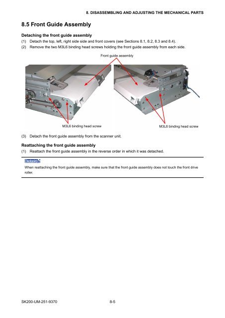
- Page 44 and 45: 8. DISASSEMBLING AND ADJUSTING THE
- Page 48 and 49: 8. DISASSEMBLING AND ADJUSTING THE
- Page 50 and 51: 8. DISASSEMBLING AND ADJUSTING THE
- Page 52 and 53: 8. DISASSEMBLING AND ADJUSTING THE
- Page 54 and 55: 8. DISASSEMBLING AND ADJUSTING THE
- Page 56 and 57: 8.13 CIS Sensor Unit AssembliesDeta
- Page 58 and 59: 8. DISASSEMBLING AND ADJUSTING THE
- Page 60 and 61: 8. DISASSEMBLING AND ADJUSTING THE
- Page 62 and 63: 8. DISASSEMBLING AND ADJUSTING THE
- Page 64 and 65: 8. DISASSEMBLING AND ADJUSTING THE
- Page 66 and 67: 8. DISASSEMBLING AND ADJUSTING THE
- Page 68 and 69: 8. DISASSEMBLING AND ADJUSTING THE
- Page 70 and 71: 8. DISASSEMBLING AND ADJUSTING THE
- Page 72 and 73: 8. DISASSEMBLING AND ADJUSTING THE
- Page 74 and 75: 8. DISASSEMBLING AND ADJUSTING THE
- Page 76 and 77: 8. DISASSEMBLING AND ADJUSTING THE
- Page 78 and 79: 9. ADJUSTMENTS USING THE SOFTWARE(5
- Page 80 and 81: 9. ADJUSTMENTS USING THE SOFTWARE9.
- Page 82 and 83: 9. ADJUSTMENTS USING THE SOFTWARE9.
- Page 84 and 85: 9. ADJUSTMENTS USING THE SOFTWARE2.
- Page 86 and 87: 9. ADJUSTMENTS USING THE SOFTWARE(7
- Page 88 and 89: 9. ADJUSTMENTS USING THE SOFTWARE(4
- Page 90 and 91: 9. ADJUSTMENTS USING THE SOFTWARE(1
- Page 92 and 93: 9. ADJUSTMENTS USING THE SOFTWARETi
- Page 94 and 95: 9. ADJUSTMENTS USING THE SOFTWARE4.
- Page 96 and 97:
9. ADJUSTMENTS USING THE SOFTWARE9.
- Page 98 and 99:
10. TROUBLESHOOTINGCause Checkpoint
- Page 101 and 102:
12. PARTS LISTS12. PARTS LISTS12.1
- Page 103 and 104:
12. PARTS LISTS12.3 Side CoverNo. P
- Page 105:
12. PARTS LISTS12.5 Feed SectionNo.
- Page 108 and 109:
12. PARTS LISTS12.8 Upper Section 2
- Page 110 and 111:
12. PARTS LISTS12.10 Rear CIS Senso
- Page 113 and 114:
12341234123412341234321125613513232
- Page 115 and 116:
SK200-UM-251-9370 13-313. BLOCK DIA
- Page 117 and 118:
SK200-UM-251-9370 13-513. BLOCK DIA
- Page 119:
SK200-UM-251-9370 13-713. BLOCK DIA
- Page 122 and 123:
SK200-UM-251-9370 13-1013. BLOCK DI
- Page 124 and 125:
SK200-UM-251-9370 13-1213. BLOCK DI
- Page 126 and 127:
SK200-UM-251-9370 13-1413. BLOCK DI
- Page 128 and 129:
SK200-UM-251-9370 13-1613. BLOCK DI
- Page 130 and 131:
13.2.2 CIS Controller Board for SK2
- Page 132 and 133:
SK200-UM-251-9370 13-2013. BLOCK DI
- Page 134 and 135:
13. BLOCK DIAGRAM AND CIRCUIT DIAGR
- Page 136 and 137:
13. BLOCK DIAGRAM AND CIRCUIT DIAGR
- Page 138 and 139:
13. BLOCK DIAGRAM AND CIRCUIT DIAGR
- Page 140 and 141:
13.2.6 Data Controller Board for SK
- Page 142 and 143:
13. BLOCK DIAGRAM AND CIRCUIT DIAGR
- Page 144 and 145:
13. BLOCK DIAGRAM AND CIRCUIT DIAGR
- Page 146 and 147:
13. BLOCK DIAGRAM AND CIRCUIT DIAGR
- Page 148 and 149:
13. BLOCK DIAGRAM AND CIRCUIT DIAGR
- Page 150 and 151:
13. BLOCK DIAGRAM AND CIRCUIT DIAGR
- Page 152 and 153:
13. BLOCK DIAGRAM AND CIRCUIT DIAGR
- Page 154 and 155:
13. BLOCK DIAGRAM AND CIRCUIT DIAGR
- Page 156 and 157:
SK200-UM-251-9370 13-4413. BLOCK DI
- Page 158 and 159:
13. BLOCK DIAGRAM AND CIRCUIT DIAGR
- Page 160 and 161:
13. BLOCK DIAGRAM AND CIRCUIT DIAGR
- Page 162 and 163:
13. BLOCK DIAGRAM AND CIRCUIT DIAGR
- Page 164:
13. BLOCK DIAGRAM AND CIRCUIT DIAGR