SK200-UM-251 - Graphtec
SK200-UM-251 - Graphtec
SK200-UM-251 - Graphtec

You also want an ePaper? Increase the reach of your titles
YUMPU automatically turns print PDFs into web optimized ePapers that Google loves.
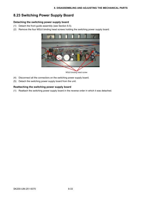
8. DISASSEMBLING AND ADJUSTING THE MECHANICAL PARTS8.23 Switching Power Supply BoardDetaching the switching power supply board(1) Detach the front guide assembly (see Section 8.5).(2) Remove the four M3L6 binding head screws holding the switching power supply board.M3L6 binding head screw(4) Disconnect all the connectors on the switching power supply board.(5) Detach the switching power supply board from the unit.Reattaching the switching power supply board(1) Reattach the switching power supply board in the reverse order in which it was detached.<strong>SK200</strong>-<strong>UM</strong>-<strong>251</strong>-9370 8-33