SK200-UM-251 - Graphtec
SK200-UM-251 - Graphtec
SK200-UM-251 - Graphtec

You also want an ePaper? Increase the reach of your titles
YUMPU automatically turns print PDFs into web optimized ePapers that Google loves.
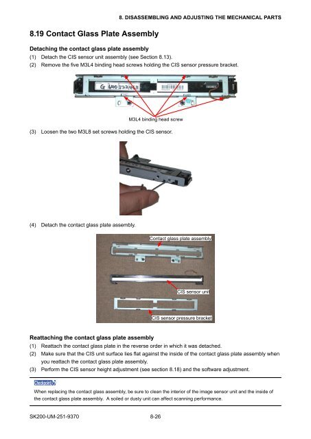
8. DISASSEMBLING AND ADJUSTING THE MECHANICAL PARTS8.19 Contact Glass Plate AssemblyDetaching the contact glass plate assembly(1) Detach the CIS sensor unit assembly (see Section 8.13).(2) Remove the five M3L4 binding head screws holding the CIS sensor pressure bracket.M3L4 binding head screw(3) Loosen the two M3L8 set screws holding the CIS sensor.(4) Detach the contact glass plate assembly.Contact glass plate assemblyCIS sensor unitCIS sensor pressure bracketReattaching the contact glass plate assembly(1) Reattach the contact glass plate in the reverse order in which it was detached.(2) Make sure that the CIS unit surface lies flat against the inside of the contact glass plate assembly whenyou reattach the contact glass plate assembly.(3) Perform the CIS sensor height adjustment (see section 8.18) and the software adjustment.CheckpointWhen replacing the contact glass assembly, be sure to clean the interior of the image sensor unit and the inside ofthe contact glass plate assembly. A soiled or dusty unit can affect scanning performance.<strong>SK200</strong>-<strong>UM</strong>-<strong>251</strong>-9370 8-26