SK200-UM-251 - Graphtec
SK200-UM-251 - Graphtec
SK200-UM-251 - Graphtec

You also want an ePaper? Increase the reach of your titles
YUMPU automatically turns print PDFs into web optimized ePapers that Google loves.
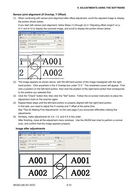
9. ADJUSTMENTS USING THE SOFTWARESensor joint alignment (X Overlap, Y Offset)(1) When continuing with sensor joint alignment after offset adjustment, scroll the adjusted image to displaythe portion shown below.If you start with sensor joint alignment, follow Steps (1) through (4) in "Adjusting offset (origin)" on p.9-11 and 9-12 to display the scanned image, and scroll to display the portion shown below.Click here first.Click here next.(2) The image appears as shown above, with the left-hand portion of the image misaligned with the righthandportion. Click anywhere in the X Overlap box under "2-3." The crosshairs cursor will appear. Firstclick a position on the left-hand portion, then click the position of the right-hand portion that correspondsto the position you selected first.(3) Click the "Check" button first, then click the "Set" button. Follow the on-screen instruction to place theadjustment chart on the scanner again.(4) Repeat these steps until the left-hand portion is properly aligned with the right-hand portion.In this task, you need to adjust the X overlap and Y offset at the same time.See "Tips for Making Fine Adjustments" on the next page if you encounter difficulties making fineadjustments.(5) Similarly, make adjustments for 3-4, 1-2, and 4-5 in this order.After finishing, close all the adjustment menu windows. Use the <strong>SK200</strong> test chart to perform a normalscan, and confirm that the image appears properly.Image after adjustments<strong>SK200</strong>-<strong>UM</strong>-<strong>251</strong>-9370 9-15