Fig. 1: Joining molding1A: CopingWood movement willnot cause jointto open, forminga crack.Fig. 2: Bisecting angles11. Draw and arc with the compasspoint at the wne'_Internal joints may be coped.18: Straight miterExternal joints must be mitered.Wood movement causes pieces toslide pass each other, not separate.2. Using the side points ascenters, drawtwo intersecting arcs...6::::::.-_____ __ .;...t
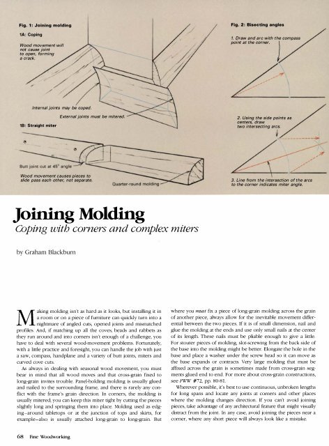
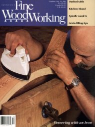
Fig. 3: Curved miterPattern doesn't line up ifmiter is a straight cut.1. Plot miter by extendinglines from patternelements onto sheetof paper./Fig_ 4: Mitering crown moldingCrown molding2. Connectintersections ofpattern lines withstraight segments.- -./' --/3. Average lines to sketch smooth curve.4. Scribe curve on molding; cut and pare to line.Holding strip to keep molding at 45°If you can cut both pieces slightly long, make a simple butt jointby springing the two pieces together. While this will keep the jointclosed, it can put a great deal of pressure on the ends of the molding,causing the joints there to fit poorly. Thus, it is better tocut the butt joint at an angle to create a straight miter, as shownin figure 1 on the facing page. If the pieces shrink, the mitereqends will slide over one another, rather than pull directly apart,exposing a gap.Joining molding at inside corners requires either mitering orcoping. Coping involves cutting one piece so it butts into the corner,then scribing the molding's profile onto the mating piece andsawing or paring the end to the exact reverse section of the piece,so it will butt into the profile. This allows the wood to move withoutbreaking the joint and means you'll only need to make onespecial cut. If it's difficult to scribe the pattern directly from theintersecting piece, you can cut a 45° inside miter on the end of onepiece and use a coping saw to cut along the curved pattern betweenthe bevel and the face of the molding. Moldings with manytiny pattern elements are often very difficult to scribe and cope.Coping also cannot be used for external corners.Mitering molding-On flat surfaces, mitering of simple profiles isa fairly straightforward matter of cutting 45° bevels. But, it can bedifficult with complicated shapes, especially when tl1e moldings intersectat angles other than 90°. The basic rule is that the angle ofthe miter must perfectly bisect the overall angle of the corner.With a 90° corner, this results in a 45° miter; if the corner of thepanel isn't 9(f, you can bisect the angle with a compass, as shownin figure 2 on the facing page, either working directly on the panelor on a sheet of paper. Using the corner as a center pOint, draw anarc that will intersect with both sides of the corner. Now, usingthese side points as centers, draw two intersecting arcs. A linebetween the intersection of the two circles and the corner willperfectly bisect the corner and indicate the miter angle. Use a bevelgauge to transfer the angle to the molding, saw proud of the lineand trim for a perfect fit.You have a slightly different problem when a curved section meetsa straight section of an identical pattern. Here the miter must becurved. To plot the line, put a piece of paper under the moldings,as shown in figure 3 above, and extend the pattern lines as shown.Connect the intersections with straight lines, then sketch in a smoothcurve, which can be scribed on the molding. Curved miters are bestcut oversize, then trimmed to the line with a knife or chisel.Straight miters may be sawn using a tablesaw or a miter box.Unless the molding will be painted, it is usually best to saw lightlyoversize and then trim to produce a perfect joint. The best way totrim the joints is with a handplane and a miter shooting board,which is just a baseboard with a step at its edge and an angledfence to support the molding. Extend the mitered end over thestep and trim it by "shooting" along the step with the plane runningon its side on the baseboard.Everything I've said about mitering so far refers to joining moldingthat fits flat against an interior surface. Crown molding, however, isoften beveled on the back so the angled molding will butt betweena wall and the ceiling or between other similar surfaces. Ifyou want to miter crown molding, you must allow for the installationangle, which is usually 45°. You can produce the needed 45°compound miter by fixing holding strips in the miter box to holdthe molding at the proper installation angle and by using regular45° slots to guide your saw. If the miter is at an odd angle, as at theend of a raking gable or an arched pediment, knock up a specialmiter box or modify your regular box by adding a guide slot angledto produce the needed compound miter angle (see figure 4above). Again, set holding strips to support the molding at theproper installation angle.DGraham Blackburn is a writer and jitrnituremaker in Soquel,Calif, and is a contn"buting editol- to Fine Woodworking.Drawings: Roland WolfJanuary/February 1989 69
- Page 3 and 4:
FineW> rktng'_' ______ ___ January/
- Page 6 and 7:
Letters (contillued)never hurt hims
- Page 8 and 9:
MetiJods of Wo rkedited and drawn b
- Page 10 and 11:
Methods of Wo rk (contillued)exampl
- Page 12 and 13:
Making a door sandwichI intend to m
- Page 14 and 15:
Q & A (colltillued)of a bad situati
- Page 16 and 17:
Pollou'-upby Dick BurrowsMore on to
- Page 18 and 19: Easy toStep by Step DrawingsBuildOn
- Page 20 and 21: (25 years)P-SOO20" PlANERSEATTLE:1
- Page 22 and 23: There areover 4,000money-savingreas
- Page 24 and 25: READY TO ASSEMBLE-SOLID-CHERRYWALNU
- Page 26 and 27: THE BARTLEYBUNDLES!AlJ.500 ·24"Ban
- Page 28 and 29: A GREAT DEA.L IMORE (f)5 HP, 3 Ph3
- Page 30 and 31: --ANTIQUE & USED TOOLSQuality, olde
- Page 32 and 33: PhoneStater--- - -[][]Ur:iTheWoodwo
- Page 34 and 35: """""',' Universal Precision Measu
- Page 36 and 37: FineWorking January/February 1989M
- Page 38 and 39: Once the backrest plaques are joine
- Page 41 and 42: Fig. 4:.1:iim.lf1lmllli.iiiiie?tII
- Page 43 and 44: Secret compartments were so common
- Page 45 and 46: -----.JFig. 4: Hanging tray below t
- Page 47 and 48: Tbree examples of the author's slid
- Page 49 and 50: worked but will maintain a crisp, s
- Page 53 and 54: SCROLL-SA W TESTCompany and model L
- Page 55 and 56: An ordinary woodturning lathe can b
- Page 57 and 58: use a dust collector, and if possib
- Page 59 and 60: I've never been especially fond of
- Page 61 and 62: and it shields your fingers from ex
- Page 63 and 64: The cabinet scraper used by the aut
- Page 65 and 66: Fig. 2: Post:Modern Table Top, 52 i
- Page 67: Fig. 3: LFI TableNut is fastened to
- Page 71 and 72: Selections from the author's sketch
- Page 73 and 74: thor anticipate problems and make f
- Page 75 and 76: Fig. 2: Air flowMoist air exits thr
- Page 77 and 78: lating fan. The idea here is to ins
- Page 79 and 80: Long prized by woodworkers for its
- Page 81 and 82: A Chinese woodworker assembles an e
- Page 83 and 84: Chinese shaping toolsThroughout Chi
- Page 85 and 86: Using a Holtzapffel ornamental lath
- Page 87 and 88: NOW! BUY BRIDGEWOOD IN CANADA . ..
- Page 89: QiUl j!! IIIc:Ul.=:c ...!!
- Page 92 and 93: 111,"11SIOPm'EI.I,lu it ....IS •
- Page 94 and 95: CARBIDE TIPPED ROUTER BITSPRCAL PRO
- Page 96: FS Tool CorporationP.o. Box 510, 21
- Page 99 and 100: ... !Ij*;::""' eMore NTS 14-5614" H
- Page 101 and 102: FI:\ISHI:\G SLPPLIESIf you have bee
- Page 103 and 104: T\UNTONPUBliCATIONS... by fellow en
- Page 105 and 106: PmeWqqQWorkingIndex to issues 66 th
- Page 107 and 108: FowlerFowler, Brian, chair by, 67,1
- Page 109 and 110: ScrewsZimmerScrews:brace driving of
- Page 111 and 112: 34-76 1 10' Uni s-l-l/2 hp ........
- Page 113 and 114: MOISTURE METERFAMOUS "MINI-LiGNO"MA
- Page 115 and 116: Dependable extra hands for all type
- Page 117 and 118: MIRRORA· THE HAND MIRRORCOMPLEMENT
- Page 119 and 120:
£'Delrl.lnc'e To Manufacture Quali