- Page 1: Cat. No. I127-EN-00B SX-V High powe
- Page 5 and 6: Condensation If the variable speed
- Page 7 and 8: 4 Omron SX inverter manual
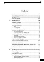
- Page 9 and 10: 10. Serial communication ..........
- Page 11 and 12: 1.3 Ordering codes Fig. 1 and Fig.
- Page 13 and 14: 1.5 Dismantling and scrapping The e
- Page 15 and 16: Models 4160 to -4800 and 6315 to 61
- Page 17 and 18: Table 5 Flow rates cooling fans Cab
- Page 19 and 20: 16 Mounting Omron SX inverter manua
- Page 21 and 22: • The screening must be connected
- Page 23 and 24: 6. Put the cable interface plate in
- Page 25 and 26: 22 Installation Omron SX inverter m
- Page 27 and 28: Table 11 L1,L2,L3 PE U, V, W Mains
- Page 29 and 30: 26 Getting Started Omron SX inverte
- Page 31 and 32: 5.2 Terminal connections The termin
- Page 33 and 34: 5.5 Connecting the Control Signals
- Page 35 and 36: 5.5.5 Current signals ((0)4-20 mA)
- Page 37 and 38: 6.1.3 Compressors Challenge OMRON S
- Page 39 and 40: Examples Different parameter sets c
- Page 41 and 42: Default settings of the Run/Stop/ E
- Page 43 and 44: from one VSD and then move the cont
- Page 45 and 46: 7.6 Pump sequencer function 7.6.1 I
- Page 47 and 48: See menu: [529] to [52H] Digital In
- Page 49 and 50: 7.6.7 Wiring Alternating Master Fig
- Page 51 and 52: 7.6.9 Functional Examples of Start/
- Page 53 and 54:
8. EMC and Machine Directive 8.1 EM
- Page 55 and 56:
9. Operation via the Control Panel
- Page 57 and 58:
menu for the parameters that are mo
- Page 59 and 60:
300 Process and Application Paramet
- Page 61 and 62:
10. Serial communication The VSD pr
- Page 63 and 64:
If a parameter is in Eint format, t
- Page 65 and 66:
Example of 15-bit fixed point forma
- Page 67 and 68:
11. Functional Description This cha
- Page 69 and 70:
Reference control [214] To control
- Page 71 and 72:
In this menu you set the general ro
- Page 73 and 74:
Range: 25 - 150% x I NOM Range: 2-1
- Page 75 and 76:
NOTE: At switching frequencies >3 k
- Page 77 and 78:
Motor I 2 t Time [233] Sets the tim
- Page 79 and 80:
2. Enable input by setting menu [23
- Page 81 and 82:
Copy All Settings to Control Panel
- Page 83 and 84:
Profibus slot/index 168/235 Fieldbu
- Page 85 and 86:
Communication information Selection
- Page 87 and 88:
1-3600 1-3600 1-3600 s Communicatio
- Page 89 and 90:
Default: 1 Selection: 1-247 Fieldbu
- Page 91 and 92:
Table 20 Selected process source To
- Page 93 and 94:
Character Ü 32 # 81 V 33 $ 82 W 34
- Page 95 and 96:
Profibus slot/index 169/218 Fieldbu
- Page 97 and 98:
Default: Range: Communication infor
- Page 99 and 100:
11.3.4 Mechanical brake control The
- Page 101 and 102:
Start release time 33C release time
- Page 103 and 104:
Communication information Modbus In
- Page 105 and 106:
IxR Comp_user [353] Only visible if
- Page 107 and 108:
+ NOTE: When Key Ref Mode is set to
- Page 109 and 110:
PID Steady State Test [388] In appl
- Page 111 and 112:
Run Time 1 All 2 Communication info
- Page 113 and 114:
Range: Communication information Ex
- Page 115 and 116:
Speed Actual Trans Min Switch on pr
- Page 117 and 118:
Ramp Alarm [413] This function inhi
- Page 119 and 120:
Fieldbus format Long, 1=1% Modbus f
- Page 121 and 122:
11.4.2 Process Protection [420] Sub
- Page 123 and 124:
Adding analogue inputs If more then
- Page 125 and 126:
AnIn1 Max [5132] Parameter to set t
- Page 127 and 128:
Communication information Modbus In
- Page 129 and 130:
11.5.2 Digital Inputs [520] Submenu
- Page 131 and 132:
Communication information AnOut 1 S
- Page 133 and 134:
Table 24 AnOut Function DC voltage
- Page 135 and 136:
Max Alarm 20 Max PreAlarm 21 Min Al
- Page 137 and 138:
Fieldbus format Modbus format Relay
- Page 139 and 140:
Default: Speed Process Val 0 Set by
- Page 141 and 142:
No. 3 4 5 6 7 8 The reference signa
- Page 143 and 144:
Example: Broken belt detection for
- Page 145 and 146:
Communication information Modbus In
- Page 147 and 148:
Timer 1 Value [649] Timer 1 Value s
- Page 149 and 150:
Torque [713] Displays the actual sh
- Page 151 and 152:
The following warnings are possible
- Page 153 and 154:
I/O board Status [728] - [72A] Indi
- Page 155 and 156:
Trip menu Copied from Description 8
- Page 157 and 158:
Unit name [923] Option to enter a n
- Page 159 and 160:
Omron SX inverter manual Functional
- Page 161 and 162:
Omron SX inverter manual Functional
- Page 163 and 164:
Omron SX inverter manual Functional
- Page 165 and 166:
12. Troubleshooting, Diagnoses and
- Page 167 and 168:
Table 28 Trip condition, their poss
- Page 169 and 170:
Table 28 Trip condition, their poss
- Page 171 and 172:
13. Options The standard options av
- Page 173 and 174:
Order number option Description 01-
- Page 175 and 176:
Safe Stop +5V Power board = X1 1 2
- Page 177 and 178:
14. Technical Data 14.1 Electrical
- Page 179 and 180:
14.2 General electrical specificati
- Page 181 and 182:
14.5 Dimensions and Weights The tab
- Page 183 and 184:
Table 43 Fuses, cable cross-section
- Page 185 and 186:
14.7.2 Fuses and cable dimensions a
- Page 187 and 188:
14.8 Control signals Table 47 Termi
- Page 189 and 190:
15. Menu List DEFAULT 244 Copy to C
- Page 191 and 192:
DEFAULT CUSTOM DEFAULT CUSTOM 399 S
- Page 193 and 194:
DEFAULT CUSTOM DEFAULT CUSTOM 569 V
- Page 195 and 196:
DEFAULT CUSTOM DEFAULT CUSTOM 85G A
- Page 197 and 198:
Index Symbols +10VDC Supply voltage
- Page 199 and 200:
(250) .............................
- Page 201 and 202:
(922) .............................