

2007_6_Nr6_EEMJ

Create successful ePaper yourself
Turn your PDF publications into a flip-book with our unique Google optimized e-Paper software.
Sustainable irrigation based on intelligent optimization of nutrients applications<br />
The irrigation module is set up at the level of<br />
the mobile arms of the automatic irrigation system<br />
and it is made up of the communication interface<br />
IPCL, the microchip control device µP, the radio<br />
receiver RR and the electro valve EV. On the MI<br />
module movement, the identification of the<br />
membership to a characterization cell is performed on<br />
the grounds of the entering its range of action. The<br />
emission power of the sensors modules MS is limited<br />
within the cell and towards its detection there<br />
interferes the criterion of the emission maximum.<br />
Following the communication settlement<br />
between the sensors module transmitter and the<br />
irrigation module receiver, the data are transmitted by<br />
the command device µP to the PLC interface, joined<br />
with the supply circuit of the operative electrical<br />
engine (Sohag et al., 2005). By the PLC transmission<br />
the useful information is received by the control<br />
centre CC, on a computer server. As a consequence of<br />
the interpretation of the response type data provided<br />
by the characterization cells sensors are taken the<br />
control decisions of reaching the limits of the<br />
nutrients concentrations and relative humidity<br />
imposed by the data basis. The quality and quantity<br />
commands are transmitted by the PLC system to the<br />
nutrients injection batteries, providing the combine<br />
irrigation agent to the pulverization nozzles, to the<br />
volume controlling electro valves belonging to the<br />
irrigation module.<br />
By the communication system PLC useful data<br />
are delivered as modulated signal. The signal is of the<br />
broadband type and the physical environment enables<br />
multiple operations roll on the same existent<br />
infrastructure.<br />
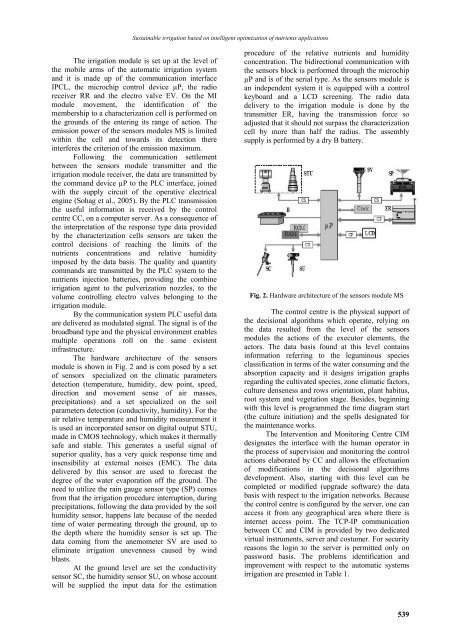
The hardware architecture of the sensors<br />
module is shown in Fig. 2 and is com posed by a set<br />
of sensors specialized on the climatic parameters<br />
detection (temperature, humidity, dew point, speed,<br />
direction and movement sense of air masses,<br />
precipitations) and a set specialized on the soil<br />
parameters detection (conductivity, humidity). For the<br />
air relative temperature and humidity measurement it<br />
is used an incorporated sensor on digital output STU,<br />
made in CMOS technology, which makes it thermally<br />
safe and stable. This generates a useful signal of<br />
superior quality, has a very quick response time and<br />
insensibility at external noises (EMC). The data<br />
delivered by this sensor are used to forecast the<br />
degree of the water evaporation off the ground. The<br />
need to utilize the rain gauge sensor type (SP) comes<br />
from that the irrigation procedure interruption, during<br />
precipitations, following the data provided by the soil<br />
humidity sensor, happens late because of the needed<br />
time of water permeating through the ground, up to<br />
the depth where the humidity sensor is set up. The<br />
data coming from the anemometer SV are used to<br />
eliminate irrigation unevenness caused by wind<br />
blasts.<br />
At the ground level are set the conductivity<br />
sensor SC, the humidity sensor SU, on whose account<br />
will be supplied the input data for the estimation<br />
procedure of the relative nutrients and humidity<br />
concentration. The bidirectional communication with<br />
the sensors block is performed through the microchip<br />
µP and is of the serial type. As the sensors module is<br />
an independent system it is equipped with a control<br />
keyboard and a LCD screening. The radio data<br />
delivery to the irrigation module is done by the<br />
transmitter ER, having the transmission force so<br />
adjusted that it should not surpass the characterization<br />
cell by more than half the radius. The assembly<br />
supply is performed by a dry B battery.<br />
Fig. 2. Hardware architecture of the sensors module MS<br />
The control centre is the physical support of<br />
the decisional algorithms which operate, relying on<br />
the data resulted from the level of the sensors<br />
modules the actions of the executor elements, the<br />
actors. The data basis found at this level contains<br />
information referring to the leguminous species<br />
classification in terms of the water consuming and the<br />
absorption capacity and it designs irrigation graphs<br />
regarding the cultivated species, zone climatic factors,<br />
culture denseness and rows orientation, plant habitus,<br />
root system and vegetation stage. Besides, beginning<br />
with this level is programmed the time diagram start<br />
(the culture initiation) and the spells designated for<br />
the maintenance works.<br />
The Intervention and Monitoring Centre CIM<br />
designates the interface with the human operator in<br />
the process of supervision and monitoring the control<br />
actions elaborated by CC and allows the effectuation<br />
of modifications in the decisional algorithms<br />
development. Also, starting with this level can be<br />
completed or modified (upgrade software) the data<br />
basis with respect to the irrigation networks. Because<br />
the control centre is configured by the server, one can<br />
access it from any geographical area where there is<br />
internet access point. The TCP-IP communication<br />
between CC and CIM is provided by two dedicated<br />
virtual instruments, server and costumer. For security<br />
reasons the login to the server is permitted only on<br />
password basis. The problems identification and<br />
improvement with respect to the automatic systems<br />
irrigation are presented in Table 1.<br />
539