

RTHD and RTAC - Trane
RTHD and RTAC - Trane
RTHD and RTAC - Trane

You also want an ePaper? Increase the reach of your titles
YUMPU automatically turns print PDFs into web optimized ePapers that Google loves.
Troubleshooting<br />
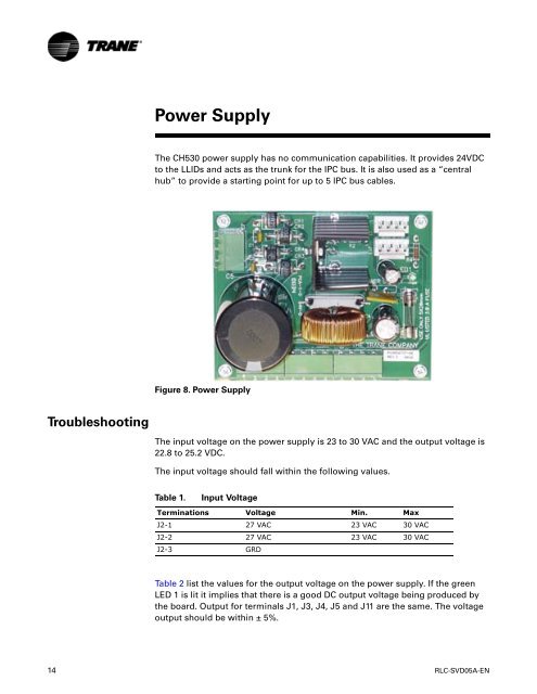
Power Supply<br />
The CH530 power supply has no communication capabilities. It provides 24VDC<br />
to the LLIDs <strong>and</strong> acts as the trunk for the IPC bus. It is also used as a “central<br />
hub” to provide a starting point for up to 5 IPC bus cables.<br />
Figure 8. Power Supply<br />
The input voltage on the power supply is 23 to 30 VAC <strong>and</strong> the output voltage is<br />
22.8 to 25.2 VDC.<br />
The input voltage should fall within the following values.<br />
Table 1. Input Voltage<br />
Terminations Voltage Min. Max<br />
J2-1 27 VAC 23 VAC 30 VAC<br />
J2-2 27 VAC 23 VAC 30 VAC<br />
J2-3 GRD<br />
Table 2 list the values for the output voltage on the power supply. If the green<br />
LED 1 is lit it implies that there is a good DC output voltage being produced by<br />
the board. Output for terminals J1, J3, J4, J5 <strong>and</strong> J11 are the same. The voltage<br />
output should be within ± 5%.<br />
14 RLC-SVD05A-EN


