

RTHD and RTAC - Trane
RTHD and RTAC - Trane
RTHD and RTAC - Trane

You also want an ePaper? Increase the reach of your titles
YUMPU automatically turns print PDFs into web optimized ePapers that Google loves.
Temperature<br />
( 0 F)<br />
150<br />
140<br />
130<br />
120<br />
110<br />
100<br />
90<br />
80<br />
70<br />
60<br />
50<br />
40<br />
30<br />
20<br />
10<br />
0<br />
Air Am bi era<br />
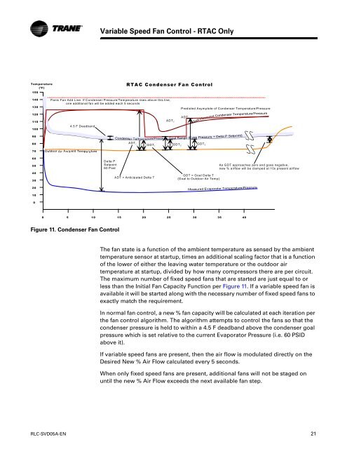
Figure 11. Condenser Fan Control<br />
Variable Speed Fan Control - <strong>RTAC</strong> Only<br />
Delta P<br />
Setpoint<br />
60 Psid<br />
<strong>RTAC</strong> Condenser Fan Control<br />
Panic Fan Add Line: If Condenser Pressure/Temperature rises above this line,<br />
one additional fan will be added each 5 seconds itteration.<br />
4.5 F Deadb<strong>and</strong><br />
er Tem perat<br />
ADT 1<br />
GDT 1<br />
ADT = Anticipated Delta T<br />
(Asymptote of Condenser Temp<br />
relative to Outdoor Air Temp)<br />
ADT 2<br />
GDT2<br />
Predicted Asymptote of Condenser Temperature/Pressure<br />
GDT = Goal Delta T<br />
(G oal to Outdoor Air Temp)<br />
0 5 10 15 20 25 30 35 40<br />
As GDT approaches zero <strong>and</strong> goes negative,<br />
new % airflow will be clamped at 10x present airflow<br />
The fan state is a function of the ambient temperature as sensed by the ambient<br />
temperature sensor at startup, times an additional scaling factor that is a function<br />
of the lower of either the leaving water temperature or the outdoor air<br />
temperature at startup, divided by how many compressors there are per circuit.<br />
The maximum number of fixed speed fans that are started are just equal to or<br />
less than the Initial Fan Capacity Function per Figure 11. If a variable speed fan is<br />
available it will be started along with the necessary number of fixed speed fans to<br />
exactly match the requirement.<br />
In normal fan control, a new % fan capacity will be calculated at each iteration per<br />
the fan control algorithm. The algorithm attempts to control the fans so that the<br />
condenser pressure is held to within a 4.5 F deadb<strong>and</strong> above the condenser goal<br />
pressure which is set relative to the current Evaporator Pressure (i.e. 60 PSID<br />
above it).<br />
If variable speed fans are present, then the air flow is modulated directly on the<br />
Desired New % Air Flow calculated every 5 seconds.<br />
When only fixed speed fans are present, additional fans will not be staged on<br />
until the new % Air Flow exceeds the next available fan step.<br />
RLC-SVD05A-EN 21<br />
ADT 3<br />
GDT 3


