

RTHD and RTAC - Trane
RTHD and RTAC - Trane
RTHD and RTAC - Trane

Create successful ePaper yourself
Turn your PDF publications into a flip-book with our unique Google optimized e-Paper software.
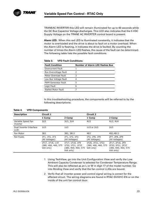
Table 4. VFD Components<br />
Variable Speed Fan Control - <strong>RTAC</strong> Only<br />
TRANEAC INVERTER this LED will remain illuminated for up to 60 seconds while<br />
the DC Bus Capacitor Voltage discharges. This LED also indicates that the 5 VDC<br />
Supply Voltage on the TRANE AC INVERTER control board is present.<br />
Alarm LED. When this red LED is illuminated constantly, it indicates that the<br />
motor is overloaded <strong>and</strong> the drive is about to fault on a motor overload. When<br />
the Alarm LED is flashing, it indicates the drive is faulted. By counting the<br />
number of times the Alarm LED flashes, the cause of the fault can be determined.<br />
The following table lists the possible fault conditions.<br />
Table 3. VFD Fault Conditions<br />
Fault Condition Number of Alarm LED flashes Bus<br />
Overcurrent Fault 1<br />
Bus Overvoltage Fault 2<br />
Motor Overload Fault 3<br />
Low Bus Voltage Fault 4<br />
PWM Generator Fault 5<br />
Logic Fault 6<br />
Stalled Motor Fault 7<br />
In this troubleshooting procedure, the components will be referred to by the<br />
following descriptions:<br />
Description Circuit 1 Circuit 2<br />
1 Comp 2 Comp 1 Comp 2 Comp<br />
Variable Speed Fan<br />
Inverter<br />
3U3 3U3, 3U4 4U3 4U3, 4U4<br />
Dual Inverter Interface<br />
LLID<br />
1U3 1U3 1U3 or 2U3 2U3<br />
Fan Motor 3B3 3B3, 3B13 4B3 4B3,4B13<br />
Fan Fuses 1F1, 1F2, 1F3<br />
(All Voltages)<br />
1F17, 1F18, 119<br />
(380, 400, 460, 575<br />
Volt only)<br />
1F1, 1F2, 1F3<br />
(All Voltages)<br />
1F17, 1F18, 1F9<br />
1F20, 1F21, 1F22<br />
(380, 400, 460, 575<br />
Volt only)<br />
1F2, 1F8, 1F9<br />
(All Voltages)<br />
1F20, 1F21, 1F22<br />
(380, 400, 460, 575<br />
Volt only)<br />
2F7, 2F8, 2F9<br />
(All Voltages)<br />
2F17, 2F18, 2F9<br />
2F20, 2F21, 2F22<br />
(380, 400, 460, 575<br />
Volt only)<br />
1 Using TechView, go into the Unit Configuration View <strong>and</strong> verify the Low<br />
Ambient Capacity Condenser is selected for Condenser Temperature Range.<br />
This will also be reflected as an L or W in digit 17 of the model number. Go<br />
into Binding View <strong>and</strong> verify that the fan control LLIDs are bound.<br />
2 Verify that all inverter power <strong>and</strong> control signal wiring is correct for the<br />
affected circuit. The wiring diagrams are found in <strong>RTAC</strong>-SVX01C-EN or on the<br />
inside of the unit fan control door.<br />
RLC-SVD05A-EN 23


