RTHD and RTAC - Trane
RTHD and RTAC - Trane
RTHD and RTAC - Trane
You also want an ePaper? Increase the reach of your titles
YUMPU automatically turns print PDFs into web optimized ePapers that Google loves.
Checkout Procedure<br />
CAUTION<br />
Compressor<br />
Damage!<br />
Optical Sensor - <strong>RTHD</strong> Only<br />
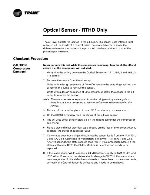
The oil level detector is located in the oil sump. The sensor uses infrared light<br />
reflected off the inside of a conical prism, back to a detector to sense the<br />
difference in refractive index of the prism /oil interface relative to that of the<br />
prism/vapor interface.<br />
Never perform this test while the compressor is running. Turn the chiller off <strong>and</strong><br />
ensure that the compressor will not start.<br />
1 Verify that the wiring between the Optical Sensor on 1A11 J2-1, 2 <strong>and</strong> 1A3 J3-<br />
1 is correct.<br />
2 Remove the sensor from the oil sump.<br />
Units with a design sequence of A0 to D0, remove the snap ring securing the<br />
sensor in the sump to remove the sensor.<br />
Units with a design sequence of E0to present, unscrew the sensor in the oil<br />
sump to remove the sensor.<br />
Note: The optical sensor is separated from the refrigerant by a clear prism,<br />
therefore, it is not necessary to recover refrigerant when removing the<br />
sensor.<br />
3 Place a mirror or white piece of paper ¼" from the face of the sensor.<br />
4 On the CH530 DynaView read the status of the oil loss sensor.<br />
5 The Oil Loss Level Sensor Status is on the reports tab under the compressor<br />
sub-menu.<br />
6 Place a piece of black electrical tape directly on the face of the sensor. After 10<br />
seconds, the status should read 'WET'<br />
7 If the status does not change, disconnect the sensor leads from the 1A11 J2-1,<br />
2 <strong>and</strong> 1A3 J3-1. Connect a 1.5 volt battery directly to 1A11 at J2-1 <strong>and</strong> J2-2.<br />
After 10 seconds, the status should read 'WET'. If so, proceed to Step 7. If the<br />
status still reads 'DRY', the Chiller Module is defective <strong>and</strong> needs to be<br />
replaced.<br />
8 If the status reads 'WET', connect a 24 VDC power supply to 1A11 at J2-1 <strong>and</strong><br />
J2-2. After 10 seconds, the status should change to 'DRY'. If the status does<br />
not change, the 1A11 is defective <strong>and</strong> needs to be replaced. If the status reads<br />
correctly, the Optical Sensor is defective <strong>and</strong> needs to be replaced.<br />
RLC-SVD05A-EN 61


