

RTHD and RTAC - Trane
RTHD and RTAC - Trane
RTHD and RTAC - Trane

Create successful ePaper yourself
Turn your PDF publications into a flip-book with our unique Google optimized e-Paper software.
Variable Speed Fan Control - <strong>RTAC</strong> Only<br />
3 Attempt to start the compressor on the desired circuit. Thirty seconds prior to<br />
compressor start, the variable speed fan inverter contactor is energized. Be<br />
sure that you can hear the fan contactor pull in. If not, attach an AC voltmeter<br />
from FR to ground on the Dual Inverter Interface LLID. Reset the control <strong>and</strong><br />
look for a 115 volt reading on the voltmeter at FR, 25 to 30 seconds prior to<br />
compressor start. If this 115 volts is verified but the contactor does not pull in,<br />
check for an open circuit in the contactor coil or an open circuit in the<br />
interconnecting wiring to the contactor.<br />
4 Check the fan motor by completely bypassing the inverter. Disconnect power<br />
from the chiller <strong>and</strong> remove the three-phase power wiring from the inverter.<br />
Connect it to the three-phase power wiring of the fan motor. Re-apply power<br />
to the unit <strong>and</strong> reset the circuit being tested. Make sure the phasing is proper<br />
when reconnecting the inverter. Twenty-five or thirty seconds before the<br />
compressor starts, the contactor that would normally apply power to the<br />
inverter should pull in <strong>and</strong> the fan should run. If the fan does not run, check<br />
the line fuses <strong>and</strong> contactor contacts.<br />
The fan will only run for approximately 30 seconds before the inverter fault<br />
will cause the contactor to drop out.<br />
5 Disconnect power from the unit <strong>and</strong> reconnect the inverter module. At the<br />
same time, check for damaged wiring or loose quick connects on the inverter.<br />
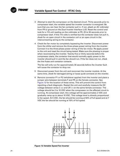
6 Remove connector P1 or P2 (whichever applies) from the inverter <strong>and</strong> place a<br />
jumper wire between terminals F <strong>and</strong> FR on the female connector. See<br />
Figure 12 for the location of these wires. This will prevent the control from<br />
reporting a fault diagnostic. Restart the unit <strong>and</strong> carefully measure the DC<br />
voltage between wires C (+) <strong>and</strong> CR (-) on the same female connector. The<br />
voltage should be 2 to 10 VDC when the compressor on the affected circuit is<br />
running. At compressor start, this voltage will be approximately 2 VDC <strong>and</strong><br />
gradually ramp up to about 10 VDC. This voltage level is directly proportional<br />
to fan speed. At 5 VDC, the fan should be running at 50% of full speed <strong>and</strong> at 7<br />
VDC the fan should be running at 70% of full speed.<br />
Figure 12.Variable Speed Fan Inverter<br />
24 RLC-SVD05A-EN


