

RTHD and RTAC - Trane
RTHD and RTAC - Trane
RTHD and RTAC - Trane

You also want an ePaper? Increase the reach of your titles
YUMPU automatically turns print PDFs into web optimized ePapers that Google loves.
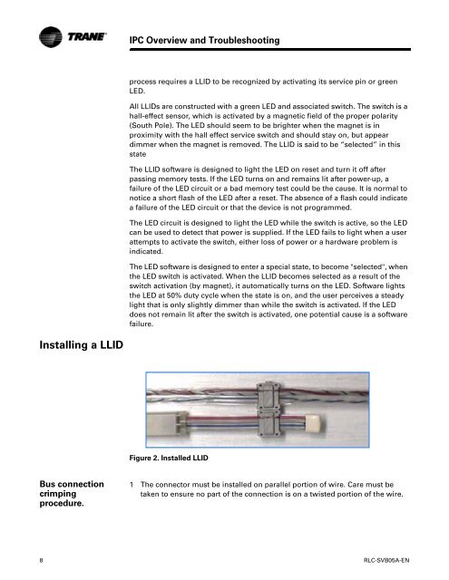
Installing a LLID<br />
Bus connection<br />
crimping<br />
procedure.<br />
IPC Overview <strong>and</strong> Troubleshooting<br />
process requires a LLID to be recognized by activating its service pin or green<br />
LED.<br />
All LLIDs are constructed with a green LED <strong>and</strong> associated switch. The switch is a<br />
hall-effect sensor, which is activated by a magnetic field of the proper polarity<br />
(South Pole). The LED should seem to be brighter when the magnet is in<br />
proximity with the hall effect service switch <strong>and</strong> should stay on, but appear<br />
dimmer when the magnet is removed. The LLID is said to be “selected” in this<br />
state<br />
The LLID software is designed to light the LED on reset <strong>and</strong> turn it off after<br />
passing memory tests. If the LED turns on <strong>and</strong> remains lit after power-up, a<br />
failure of the LED circuit or a bad memory test could be the cause. It is normal to<br />
notice a short flash of the LED after a reset. The absence of a flash could indicate<br />
a failure of the LED circuit or that the device is not programmed.<br />
The LED circuit is designed to light the LED while the switch is active, so the LED<br />
can be used to detect that power is supplied. If the LED fails to light when a user<br />
attempts to activate the switch, either loss of power or a hardware problem is<br />
indicated.<br />
The LED software is designed to enter a special state, to become "selected", when<br />
the LED switch is activated. When the LLID becomes selected as a result of the<br />
switch activation (by magnet), it automatically turns on the LED. Software lights<br />
the LED at 50% duty cycle when the state is on, <strong>and</strong> the user perceives a steady<br />
light that is only slightly dimmer than while the switch is activated. If the LED<br />
does not remain lit after the switch is activated, one potential cause is a software<br />
failure.<br />
Figure 2. Installed LLID<br />
1 The connector must be installed on parallel portion of wire. Care must be<br />
taken to ensure no part of the connection is on a twisted portion of the wire.<br />
8 RLC-SVB05A-EN


