RTHD and RTAC - Trane
RTHD and RTAC - Trane
RTHD and RTAC - Trane
Create successful ePaper yourself
Turn your PDF publications into a flip-book with our unique Google optimized e-Paper software.
<strong>RTAC</strong> Chillers<br />
Check out procedure for <strong>RTAC</strong><br />
� WARNING<br />
Live Electrical<br />
Components!<br />
Under/Over<br />
Voltage<br />
Transformer<br />
Checkout<br />
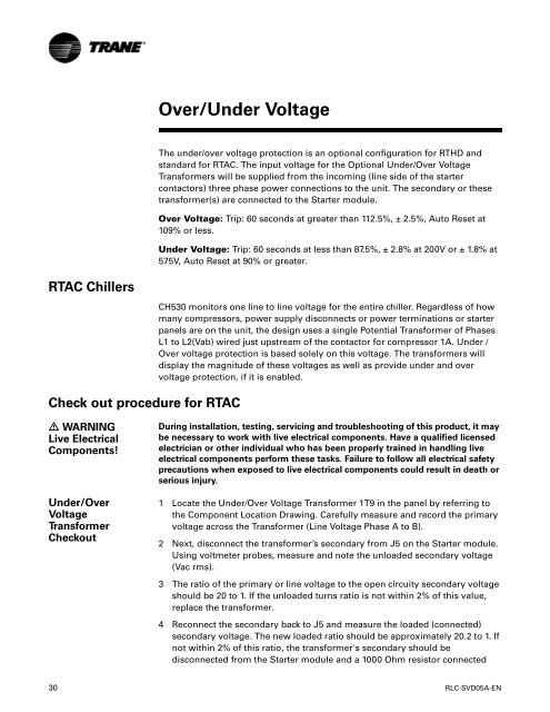
Over/Under Voltage<br />
The under/over voltage protection is an optional configuration for <strong>RTHD</strong> <strong>and</strong><br />
st<strong>and</strong>ard for <strong>RTAC</strong>. The input voltage for the Optional Under/Over Voltage<br />
Transformers will be supplied from the incoming (line side of the starter<br />
contactors) three phase power connections to the unit. The secondary or these<br />
transformer(s) are connected to the Starter module.<br />
Over Voltage: Trip: 60 seconds at greater than 112.5%, ± 2.5%, Auto Reset at<br />
109% or less.<br />
Under Voltage: Trip: 60 seconds at less than 87.5%, ± 2.8% at 200V or ± 1.8% at<br />
575V, Auto Reset at 90% or greater.<br />
CH530 monitors one line to line voltage for the entire chiller. Regardless of how<br />
many compressors, power supply disconnects or power terminations or starter<br />
panels are on the unit, the design uses a single Potential Transformer of Phases<br />
L1 to L2(Vab) wired just upstream of the contactor for compressor 1A. Under /<br />
Over voltage protection is based solely on this voltage. The transformers will<br />
display the magnitude of these voltages as well as provide under <strong>and</strong> over<br />
voltage protection, if it is enabled.<br />
During installation, testing, servicing <strong>and</strong> troubleshooting of this product, it may<br />
be necessary to work with live electrical components. Have a qualified licensed<br />
electrician or other individual who has been properly trained in h<strong>and</strong>ling live<br />
electrical components perform these tasks. Failure to follow all electrical safety<br />
precautions when exposed to live electrical components could result in death or<br />
serious injury.<br />
1 Locate the Under/Over Voltage Transformer 1T9 in the panel by referring to<br />
the Component Location Drawing. Carefully measure <strong>and</strong> record the primary<br />
voltage across the Transformer (Line Voltage Phase A to B).<br />
2 Next, disconnect the transformer’s secondary from J5 on the Starter module.<br />
Using voltmeter probes, measure <strong>and</strong> note the unloaded secondary voltage<br />
(Vac rms).<br />
3 The ratio of the primary or line voltage to the open circuity secondary voltage<br />
should be 20 to 1. If the unloaded turns ratio is not within 2% of this value,<br />
replace the transformer.<br />
4 Reconnect the secondary back to J5 <strong>and</strong> measure the loaded (connected)<br />
secondary voltage. The new loaded ratio should be approximately 20.2 to 1. If<br />
not within 2% of this ratio, the transformer's secondary should be<br />
disconnected from the Starter module <strong>and</strong> a 1000 Ohm resistor connected<br />
30 RLC-SVD05A-EN


