UC4™ Total Control™ Automatic Boom Height Technical ... - Norac
UC4™ Total Control™ Automatic Boom Height Technical ... - Norac
UC4™ Total Control™ Automatic Boom Height Technical ... - Norac

Create successful ePaper yourself
Turn your PDF publications into a flip-book with our unique Google optimized e-Paper software.
4.5 CONTROL PANEL<br />
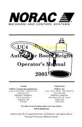
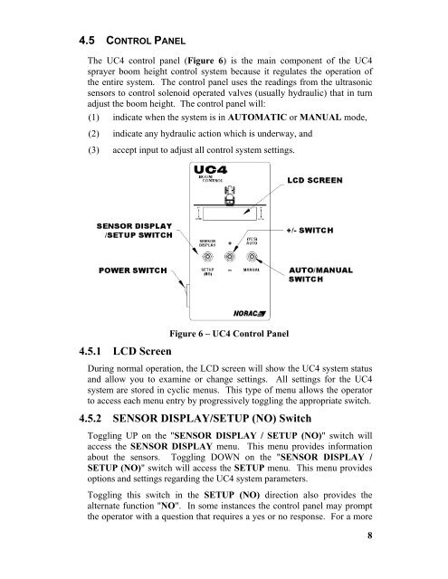
The UC4 control panel (Figure 6) is the main component of the UC4<br />
sprayer boom height control system because it regulates the operation of<br />
the entire system. The control panel uses the readings from the ultrasonic<br />
sensors to control solenoid operated valves (usually hydraulic) that in turn<br />
adjust the boom height. The control panel will:<br />
(1) indicate when the system is in AUTOMATIC or MANUAL mode,<br />
(2) indicate any hydraulic action which is underway, and<br />
(3) accept input to adjust all control system settings.<br />
4.5.1 LCD Screen<br />
Figure 6 – UC4 Control Panel<br />
During normal operation, the LCD screen will show the UC4 system status<br />
and allow you to examine or change settings. All settings for the UC4<br />
system are stored in cyclic menus. This type of menu allows the operator<br />
to access each menu entry by progressively toggling the appropriate switch.<br />
4.5.2 SENSOR DISPLAY/SETUP (NO) Switch<br />
Toggling UP on the "SENSOR DISPLAY / SETUP (NO)" switch will<br />
access the SENSOR DISPLAY menu. This menu provides information<br />
about the sensors. Toggling DOWN on the "SENSOR DISPLAY /<br />
SETUP (NO)" switch will access the SETUP menu. This menu provides<br />
options and settings regarding the UC4 system parameters.<br />
Toggling this switch in the SETUP (NO) direction also provides the<br />
alternate function "NO". In some instances the control panel may prompt<br />
the operator with a question that requires a yes or no response. For a more<br />
8