UC4™ Total Control™ Automatic Boom Height Technical ... - Norac
UC4™ Total Control™ Automatic Boom Height Technical ... - Norac
UC4™ Total Control™ Automatic Boom Height Technical ... - Norac

You also want an ePaper? Increase the reach of your titles
YUMPU automatically turns print PDFs into web optimized ePapers that Google loves.
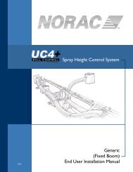
4 GENERAL SYSTEM DESCRIPTION<br />
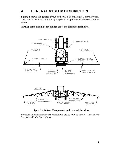
Figure 1 shows the general layout of the UC4 <strong>Boom</strong> <strong>Height</strong> Control system.<br />
The function of each of the major system components is described in this<br />
section.<br />
NOTE: Some kits may not include all of the components shown.<br />
LEFT OUTER<br />
SENSOR (LO)<br />
POWER CABLE<br />
SENSOR TRUNK<br />
CABLE<br />
SENSOR BRACKET<br />
CONTROL PANEL<br />
RIGHT OUTER<br />
SENSOR (RO)<br />
SENSOR BRANCH<br />
CABLE CONNECTION<br />
OPTIONAL LEFT<br />
OPTIONAL<br />
INNER SENSOR (LI) OPTIONAL RIGHT<br />
MAIN ROLL<br />
MAIN LIFT<br />
INNER SENSOR (RI)<br />
SENSOR (MR)<br />
SENSOR (ML)<br />
LEFT OUTER<br />
SENSOR (LO)<br />
MAIN ROLL<br />
SENSOR (MR)<br />
OPTIONAL LEFT<br />
INNER SENSOR (LI)<br />
OPTIONAL RIGHT<br />
INNER SENSOR (RI)<br />
OPTIONAL MAIN<br />
LIFT SENSOR (ML)<br />
Figure 1 - System Components and General Location<br />
RIGHT OUTER<br />
SENSOR (RO)<br />
For more information on each component, please refer to the UC4 Installation<br />
Manual and UC4 Quick Guide.<br />
4