UC4™ Total Control™ Automatic Boom Height Technical ... - Norac
UC4™ Total Control™ Automatic Boom Height Technical ... - Norac
UC4™ Total Control™ Automatic Boom Height Technical ... - Norac

Create successful ePaper yourself
Turn your PDF publications into a flip-book with our unique Google optimized e-Paper software.
5 SYSTEM OPERATION<br />
This section outlines the UC4 system’s features and controls during field<br />
operation. Before you can operate your UC4 system in AUTO mode, it<br />
needs to be configured either automatically or manually. If your control<br />
panel shows the power up sequence below and will allow AUTO mode, it<br />
has been configured. If your panel shows different messages after being<br />
powered up or will not allow AUTO mode, it will attempt to begin or<br />
resume <strong>Automatic</strong> System Setup. Refer to Section 8 for System Setup<br />
instructions.<br />
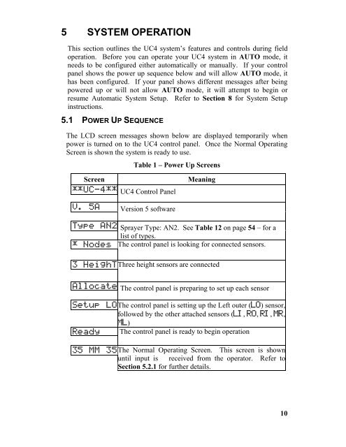
5.1 POWER UP SEQUENCE<br />
The LCD screen messages shown below are displayed temporarily when<br />
power is turned on to the UC4 control panel. Once the Normal Operating<br />
Screen is shown the system is ready to use.<br />
Table 1 – Power Up Screens<br />
Screen Meaning<br />
** U C - 4 * * UC4 Control Panel<br />
V. 5 A Version 5 software<br />
Typ e A N 2 Sprayer Type: AN2. See Table 12 on page 54 – for a<br />
list of types.<br />
* N o d e s The control panel is looking for connected sensors.<br />
3 H e i g h T Three height sensors are connected<br />
Al l o c a t e The control panel is preparing to set up each sensor<br />
Se t u p L O The control panel is setting up the Left outer (LO) sensor,<br />
followed by the other attached sensors (LI, RO, RI, MR,<br />
ML)<br />
Re a d y The control panel is ready to begin operation<br />
35 M M 3 5 The Normal Operating Screen. This screen is shown<br />
until input is received from the operator. Refer to<br />
Section 5.2.1 for further details.<br />
10