UC4™ Total Control™ Automatic Boom Height Technical ... - Norac
UC4™ Total Control™ Automatic Boom Height Technical ... - Norac
UC4™ Total Control™ Automatic Boom Height Technical ... - Norac
Create successful ePaper yourself
Turn your PDF publications into a flip-book with our unique Google optimized e-Paper software.
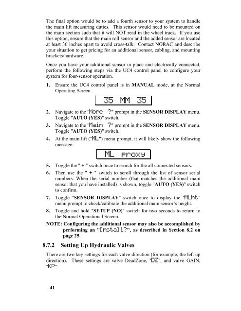
The final option would be to add a fourth sensor to your system to handle<br />
the main lift measuring duties. This sensor would need to be mounted on<br />
the main section such that it will NOT read in the wheel track. If you use<br />
this option, ensure that the main roll sensor and the added sensor are located<br />
at least 36 inches apart to avoid cross-talk. Contact NORAC and describe<br />
your situation to get pricing for an additional sensor, cabling, and mounting<br />
brackets/hardware.<br />
Once you have your additional sensor in place and electrically connected,<br />
perform the following steps via the UC4 control panel to configure your<br />
system for four-sensor operation.<br />
1. Ensure the UC4 control panel is in MANUAL mode, at the Normal<br />
Operating Screen.<br />
41<br />
↓↓35 MM 35↓<br />
2. Navigate to the "More ?" prompt in the SENSOR DISPLAY menu.<br />
Toggle "AUTO (YES)" switch.<br />
3. Navigate to the "Main ?" prompt in the SENSOR DISPLAY menu.<br />
Toggle "AUTO (YES)" switch.<br />
4. At the main lift ("ML") menu prompt, it will likely show the following<br />
message:<br />
↓↓ML proxy↓<br />
5. Toggle the " + " switch once to search for the all connected sensors.<br />
6. Then use the " + " switch to scroll through the list of sensor serial<br />
numbers. When the serial number (that matches the additional main<br />
sensor that you have installed) is shown, toggle "AUTO (YES)" switch<br />
to confirm.<br />
7. Toggle "SENSOR DISPLAY" switch once to display the "MLht"<br />
menu prompt to check/calibrate the additional main sensor’s height.<br />
8. Toggle and hold "SETUP (NO)" switch for two seconds to return to<br />
the Normal Operational Screen.<br />
NOTE: Configuring the additional sensor may also be accomplished by<br />
performing an "Install?", as described in Section 8.2 on<br />
page 25.<br />
8.7.2 Setting Up Hydraulic Valves<br />
There are two key settings for each valve direction (for example, the left up<br />
direction). These settings are valve DeadZone, "DZ", and valve GAIN,<br />
"KP".


