atw - International Journal for Nuclear Power | 2.2024
Internationale Entwicklungen und Trends
Internationale Entwicklungen und Trends

You also want an ePaper? Increase the reach of your titles
YUMPU automatically turns print PDFs into web optimized ePapers that Google loves.
Environment and Safety<br />
61<br />
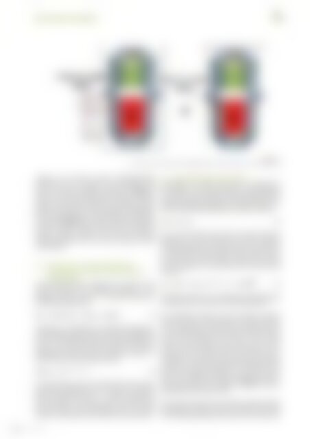
Fig. 2.<br />
Ex-vessel neutron dosimetry system(EVND) and Surveillance capsule in nozzle region<br />
capsule and Ex-vessel neutron dosimetry(EVND)<br />
measured in the core region to the calculated result<br />
from the neutron transport calculation. (Figure 1)<br />
shows Ex-vessel neutron dosimetry system in beltline<br />
region. If the neutron dosimeter is attached to reactor<br />
pressure vessel nozzle, accurate results can be obtained,<br />
but it is impossible due to spatial limitation. There<strong>for</strong>e,<br />
as shown in (Figure 2), accurate result can be obtained<br />
from the measured value of upper part of surveillance<br />
capsule neutron monitor and Ex-vessel neutron<br />
dosimetry(EVND) close to the reactor pressure vessel<br />
nozzle region.<br />
2.3 Determination of Adjusted Reference<br />
Temperature <strong>for</strong> Reactor Vessel Inlet and<br />
Outlet Nozzle<br />
The adjusted reference temperatures (ARTs) <strong>for</strong> the<br />
nozzle materials are calculated according to the<br />
Regulatory Guide 1.99 Rev. 2 [3] . The ARTs are given by<br />
the following expression:<br />
ART = Initial RT NDT + ∆RT NDT + Margin (2)<br />
Initial RT NDT of equation (2) is reference temperature<br />
of unirradiated nozzle material and is determined based<br />
on the certified material test reports (CMTRs) <strong>for</strong><br />
reactor vessel inlet and outlet nozzles. The reference<br />
temperature shift by neutron irradiation, ∆RT NDT , is<br />
determined by the following equation:<br />
∆RT NDT = CF × f (0.28 – 0.1·logf) (3)<br />
CF is the chemistry factor (CF) derived from the Copper<br />
and Nickel weight percent (wt. %) values. f is neutron<br />
fluence value (E+19 n/cm2, E > 1 MeV) at 48EFPY and<br />
was calculated at the lowest extent of weld location<br />
between nozzle and intermediate shell. The lowest<br />
extent of weld location was chosen <strong>for</strong> conservatism.<br />
2.4 Allowable Pressure Calculation<br />
According to the ASME Code Section XI Appendix G<br />
2013 edition [4] , the stress which have to be considered<br />
in nozzle P-T limit evaluation are both internal pressure<br />
loading and thermal loading. For level A&B service condition,<br />
the following requirement shall be satisfied.<br />
2K Ip + K It < K Ia (4)<br />
K Ip is stress intensity factor due to internal pressure<br />
loading, K It is stress intensity factor due to thermal<br />
transient loading. In this study, K Ia fracture toughness<br />
is considered in the generation of the nozzles corner<br />
P-T limits. Thus, <strong>for</strong> the nozzle P-T limit curves, the K Ia<br />
fracture toughness is calculated based on the following<br />
equation [4] .<br />
K Ia = 26.78 + 1.223 * e (0.0145(T–RTndt + 160)) ksi√in(5)<br />
Allowable pressure can be obtained by defining the K Ip<br />
of equation (4) as a function of internal pressure.<br />
The applicable pressure and the thermal transient<br />
stress are used to calculate pressure and the thermal<br />
stress intensity factor. K Ip and K It , at the nozzle corner<br />
cut are determined based on a finite element analysis<br />
because the maximum stress occurs in the nozzle<br />
corner. Only the cool-down transient stresses are considered<br />
since the inside surface of the nozzle corner<br />
would be in a tensile stress state during the cool-down<br />
transient. The stress intensity factor calculation <strong>for</strong> the<br />
nozzle corner regions is based on a 1/4t circular corner<br />
flaw, as per ASME code Section XI Appendix G 2013 [4]<br />
edition postulated flaw guidelines. (Figure 3) shows<br />
postulated nozzle corner crack.<br />
The stress intensity factor calculation method includes<br />
postulating an inside surface 1/4t nozzle corner flaw<br />
and calculating through-wall nozzle corner stresses <strong>for</strong><br />
Vol. 69 (2024)