Modular units
Modular units
Modular units

You also want an ePaper? Increase the reach of your titles
YUMPU automatically turns print PDFs into web optimized ePapers that Google loves.
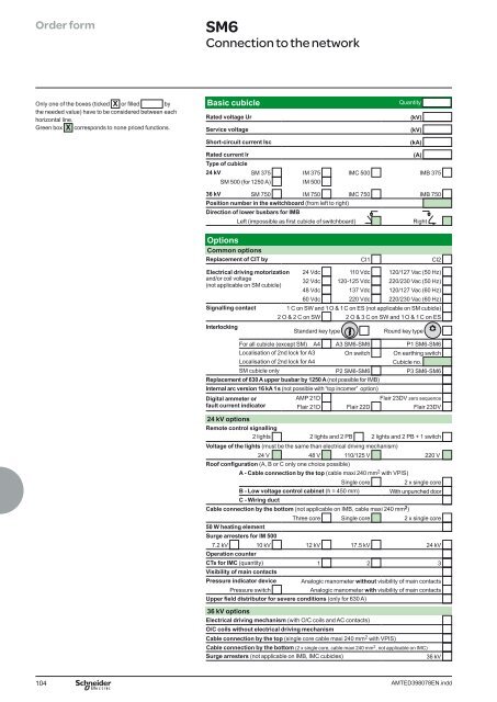
Order form SM6<br />
Connection to the network<br />
Only one of the boxes (ticked X or fi lled by<br />
the needed value) have to be considered between each<br />
horizontal line.<br />
Green box X corresponds to none priced functions.<br />
Basic cubicle Quantity<br />
Rated voltage Ur (kV)<br />
Service voltage (kV)<br />
Short-circuit current Isc (kA)<br />
Rated current Ir (A)<br />
Type of cubicle<br />
24 kV SM 375 IM 375 IMC 500 IMB 375<br />
SM 500 (for 1250 A) IM 500<br />
36 kV SM 750 IM 750 IMC 750 IMB 750<br />
Position number in the switchboard (from left to right)<br />
Direction of lower busbars for IMB<br />
Left (impossible as fi rst cubicle of switchboard) Right<br />
Options<br />
Common options<br />
Replacement of CIT by CI1 CI2<br />
Electrical driving motorization 24 Vdc 110 Vdc 120/127 Vac (50 Hz)<br />
and/or coil voltage<br />
(not applicable on SM cubicle)<br />
32 Vdc<br />
48 Vdc<br />
120-125 Vdc<br />
137 Vdc<br />
220/230 Vac (50 Hz)<br />
120/127 Vac (60 Hz)<br />
60 Vdc 220 Vdc 220/230 Vac (60 Hz)<br />
Signalling contact 1 C on SW and 1 O & 1 C on ES (not applicable on SM cubicle)<br />
Interlocking<br />
2 O & 2 C on SW 2 O & 3 C on SW and 1 O & 1 C on ES<br />
Standard key type Round key type<br />
For all cubicle (except SM) A4 A3 SM6-SM6 P1 SM6-SM6<br />
Localisation of 2nd lock for A3 On switch On earthing switch<br />
Localisation of 2nd lock for A4 Cubicle no.<br />
SM cubicle only P2 SM6-SM6 P3 SM6-SM6<br />
Replacement of 630 A upper busbar by 1250 A (not possible for IMB)<br />
Internal arc version 16 kA 1 s (not possible with “top incomer” option)<br />
Digital ammeter or<br />
fault current indicator<br />
AMP 21D Flair 23DV zero sequence<br />
Flair 21D Flair 22D Flair 23DV<br />
24 kV options<br />
Remote control signalling<br />
2 lights 2 lights and 2 PB 2 lights and 2 PB + 1 switch<br />
Voltage of the lights (must be the same than electrical driving mechanism)<br />
24 V 48 V 110/125 V 220 V<br />
Roof confi guration (A, B or C only one choice possible)<br />
A - Cable connection by the top (cable maxi 240 mm2 with VPIS)<br />
Single core 2 x single core<br />
B - Low voltage control cabinet (h = 450 mm) With unpunched door<br />
C - Wiring duct<br />
Cable connection by the bottom (not applicable on IMB, cable maxi 240 mm2 )<br />
Three core Single core 2 x single core<br />
50 W heating element<br />
Surge arresters for IM 500<br />
7.2 kV 10 kV 12 kV 17.5 kV 24 kV<br />
Operation counter<br />
CTs for IMC (quantity) 1 2 3<br />
Visibility of main contacts<br />
Pressure indicator device Analogic manometer without visibility of main contacts<br />
Pressure switch Analogic manometer with visibility of main contacts<br />
Upper fi eld distributor for severe conditions (only for 630 A)<br />
36 kV options<br />
Electrical driving mechanism (with O/C coils and AC contacts)<br />
O/C coils without electrical driving mechanism<br />
Cable connection by the top (single core cable maxi 240 mm 2 with VPIS)<br />
Cable connection by the bottom (2 x single core, cable maxi 240 mm 2 , not applicable on IMC)<br />
Surge arresters (not applicable on IMB, IMC cubicles) 36 kV<br />
104 AMTED398078EN.indd

![Data Center Solutions [EN011] ZPAS - SLO Latvia](https://img.yumpu.com/15723906/1/185x260/data-center-solutions-en011-zpas-slo-latvia.jpg?quality=85)