Modular units
Modular units
Modular units

You also want an ePaper? Increase the reach of your titles
YUMPU automatically turns print PDFs into web optimized ePapers that Google loves.
DE56655<br />
DE56656EN<br />
Characteristics of<br />
the functional <strong>units</strong><br />
SW1 SW3 SW2<br />
“Normal” position<br />
SW1 SW3 SW2<br />
Active coupling<br />
V2<br />
V1<br />
O<br />
F<br />
O<br />
F<br />
O<br />
T1<br />
SW2 voltage<br />
SW1 voltage<br />
SW1<br />
T3<br />
SW3<br />
T2<br />
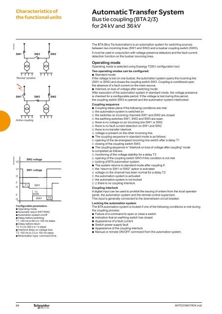
Confi gurable parameters:<br />
b Operating mode<br />
b Automatic return SW1/SW2<br />
b Automation system on/off<br />
b Delay before switching<br />
T1: 100 ms to 60 s in 100 ms steps<br />
b Delay before return<br />
T2: 5 s to 300 s in 1 s steps<br />
b Interlock delay on voltage loss<br />
T3: 100 ms to 3 s in 100 ms steps<br />
b Motorisation type: command time.<br />
Automatic Transfer System<br />
Bus tie coupling (BTA 2/3)<br />
for 24 kV and 36 kV<br />
The BTA (Bus Tie Automatism) is an automation system for switching sources<br />
between two incoming lines (SW1 and SW2) and a busbar coupling switch (SW3).<br />
It must be used in conjunction with voltage presence detectors and the fault current<br />
detection function on the busbar incoming lines.<br />
Operating mode<br />
Operating mode is selected using Easergy T200 I confi guration tool.<br />
Two operating modes can be confi gured:<br />
b Standard mode:<br />
If the voltage is lost on one busbar, the automation system opens the incoming line<br />
(SW1 or SW2) and closes the coupling switch SW3. Coupling is conditional upon<br />
the absence of a fault current on the main source.<br />
b Interlock on loss of voltage after switching mode:<br />
After execution of the automation system in standard mode, the voltage presence<br />
is checked for a confi gurable period. If the voltage is lost during this period,<br />
the coupling switch SW3 is opened and the automation system interlocked.<br />
Coupling sequence<br />
b Coupling takes place if the following conditions are met:<br />
v the automation system is switched on<br />
v the switches on incoming channels SW1 and SW2 are closed<br />
v the earthing switches SW1, SW2 and SW3 are open<br />
v there is no voltage on an incoming line SW1 or SW2<br />
v there is no fault current detection on SW1 and SW2<br />
v there is no transfer interlock<br />
v voltage is present on the other incoming line.<br />
b The coupling sequence in standard mode is as follows:<br />
v opening of the de-energised incoming line switch after a delay T1<br />
v closing of the coupling switch SW3.<br />
b The coupling sequence in “Interlock on loss of voltage after coupling” mode<br />
is completed as follows:<br />
v monitoring of the voltage stability for a delay T3<br />
v opening of the coupling switch SW3 if this condition is not met<br />
v locking of BTA automation system.<br />
b The system returns to standard mode after coupling if:<br />
v the “return to SW1 or SW2” option is activated<br />
v voltage on the channel has been normal for a delay T2<br />
v the automation system is activated<br />
v the automation system is not locked<br />
vv there is no coupling interlock.<br />
Coupling interlock<br />
A digital input can be used to prohibit the issuing of orders from the local operator<br />
panel, the automation system and the remote control supervisor.<br />
This input is generally connected to the downstream circuit breaker.<br />
Locking the automation system<br />
The BTA automation system is locked if one of the following conditions is met during<br />
the coupling process:<br />
b Failure of a command to open or close a switch<br />
b Indication that an earthing switch has closed<br />
b Appearance of a fault current<br />
b Switch power supply fault<br />
b Appearance of the coupling interlock<br />
b Manual or remote ON/OFF command from the automation system.<br />
64 AMTED398078EN.indd

![Data Center Solutions [EN011] ZPAS - SLO Latvia](https://img.yumpu.com/15723906/1/185x260/data-center-solutions-en011-zpas-slo-latvia.jpg?quality=85)