Modular units
Modular units
Modular units

Create successful ePaper yourself
Turn your PDF publications into a flip-book with our unique Google optimized e-Paper software.
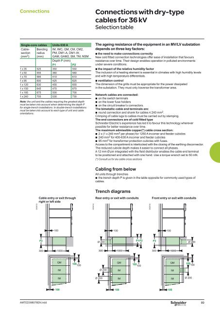
Connections Connections with dry-type<br />
cables for 36 kV<br />
Selection table<br />
Single-core cables Units 630 A<br />
Cablesection<br />
(mm 2 )<br />
Bending<br />
radius<br />
(mm)<br />
DE59723<br />
AMTED398078EN.indd<br />
Cable entry or exit through<br />
right or left side<br />
P2<br />
300<br />
IM, IMC, QM, CM, CM2,<br />
PM, DM1-A, DM1-W,<br />
GAM, GAM2, SM, TM, NSM<br />
Depth P (mm)<br />
P1 P2<br />
1 x 35 525 350 550<br />
1 x 50 555 380 580<br />
1 x 70 585 410 610<br />
1 x 95 600 425 625<br />
1 x 120 630 455 655<br />
1 x 150 645 470 670<br />
1 x 185 675 500 700<br />
1 x 240 705 530 730<br />
Note: the unit and the cables requiring the greatest depth<br />
must be taken into account when determining the depth P<br />
for single-trench installations. In double-trench installations<br />
must be taken into account to each type of unit and cable<br />
orientations.<br />
100<br />
1000<br />
QM<br />
IM<br />
IM<br />
100<br />
100<br />
100<br />
DE59724<br />
The ageing resistance of the equipment in an MV/LV substation<br />
depends on three key factors:<br />
b the need to make connections correctly<br />
New cold fi tted connection technologies offer ease of installation that favours<br />
resistance over time. Their design enables operation in polluted environments<br />
under severe conditions.<br />
b the impact of the relative humidity factor<br />
The inclusion of a heating element is essential in climates with high humidity levels<br />
and with high temperature differentials.<br />
b ventilation control<br />
The dimension of the grills must be appropriate for the power dissipated<br />
in the substation. They must only traverse the transformer area.<br />
Network cables are connected:<br />
b on the switch terminals<br />
b on the lower fuse holders<br />
b on the circuit breaker’s connectors.<br />
The bimetallic cable end terminals are:<br />
b round connection and shank for cables y 240 mm2 .<br />
Crimping of cable lugs to cables must be carried out by stamping.<br />
The end connectors are of cold fi tted type<br />
Schneider Electric’s experience has led it to favour this technology wherever<br />
possible for better resistance over time.<br />
The maximum admissible copper(*) cable cross section:<br />
b 2 x (1 x 240 mm2 per phase) for 1250 A incomer and feeder cubicles<br />
b 240 mm2 for 400-630 A incomer and feeder cubicles<br />
b 95 mm2 for transformer protection cubicles with fuses.<br />
Access to the compartment is interlocked with the closing of the earthing disconnector.<br />
The reduced cubicle depth makes it easier to connect all phases.<br />
A 12 mm Ø pin integrated with the fi eld distributor enables the cable end terminal<br />
to be positioned and attached with one hand. Use a torque wrench set to 50 mN.<br />
(*) Consult us for alu cable cross sections<br />
Cabling from below<br />
All <strong>units</strong> through trenches<br />
b the trench depth P is given in the table opposite for commonly used types of<br />
cables.<br />
Trench diagrams<br />
Rear entry or exit with conduits Front entry or exit with conduits<br />
Ø 200<br />
Ø 200<br />
Ø 200<br />
100<br />
1000<br />
QM<br />
IM<br />
IM<br />
100<br />
P1P2<br />
100<br />
100<br />
DE59725<br />
P2<br />
300<br />
100<br />
100<br />
1000<br />
QM<br />
IM<br />
IM<br />
Ø 200<br />
100<br />
100<br />
Ø 200<br />
89


![Data Center Solutions [EN011] ZPAS - SLO Latvia](https://img.yumpu.com/15723906/1/185x260/data-center-solutions-en011-zpas-slo-latvia.jpg?quality=85)