DE5961 DE59662 Installation Dimensions and weights for 36 kV (1) The depth measures are given for the fl oor surface. (2) The depth in these <strong>units</strong> are 1615 mm with the enlarged low voltage compartment. (3) The depth in these <strong>units</strong> are 1500 mm with the standard low voltage compartment. 150 150 A B 14.2 x 25 50 1100 1400 IM, SM, IMC, QM, PM, IMB, GBM, GAM, GAM2, GBC-A,GBC-B QMB, QMC <strong>units</strong> 1400 32 100 2250 DE59663 Dimensions and weights Unit type Height Width Depth (1) Weight (mm) (mm) (mm) (kg) IM, SM 2250 750 1400 (3) 310 IMC, IMB 2250 750 1400 (2) 420 QM, PM, QMB 2250 750 1400 (3) 330 QMC 2250 1000 1400 (3) 420 DM1-A 2250 1000 1400 (2) 600 DM1-D 2250 1000 1400 (2) 560 DM1-W 2250 1000 1400 (2) 660 NSM 2250 1500 1400 (2) 620 GIM 2250 250 1400 90 DM2 2250 1500 1400 (2) 900 DM2-W 2250 1500 1400 (2) 920 CM, CM2 2250 750 1400 (2) 460 GBC-A, GBC-B 2250 750 1400 (3) 420 GBM 2250 750 1400 (3) 260 GAM2 2250 750 1400 (3) 250 GAM 2250 750 1400 (3) 295 Ground preparation Units may be installed on ordinary concrete grounds, with or without trenches depending on the type and cross-section of cables. Required civil works are identical for all <strong>units</strong>. Fixing of <strong>units</strong> With each other The <strong>units</strong> are simply bolted together to form the MV switchboard (bolts supplied). Busbar connections are made using a torque wrench set to 28 mN. On the ground b for switchboards comprising up to three <strong>units</strong>, the four corners of the switchboard must be secured to the ground using: v bolts (not supplied) screwed into nuts set into the ground using a sealing pistol v screw rods grouted into the ground b for switchboards comprising more than three <strong>units</strong>, the number and position of fi xing points depends on local criteria (earthquake withstand capacities, etc.) b position of fi xing holes depends on the width of <strong>units</strong>. Unit type A (mm) B (mm) IM, IMC, IMB, QM, PM, SM, CM, CM2, TM GBC-A, GBC-B, GBM, GAM2, IMB, GAM, QMB 750 650 DM1-A, DM1-D, DM1-W, QMC 1000 900 DM2, NSM, DM2-W 1500 1400 GIM 250 150 Dimensions CM, CM2, NSM <strong>units</strong> DM1-A, DM1-D, DM2, DM1-W, DM2-W <strong>units</strong> 1400 32 96 AMTED398078EN.indd 215 2250 DE59664 215 1400 32 230 2250
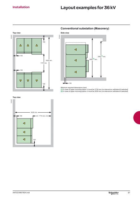
DE59665 DE59667 Installation Layout examples for 36 kV Top view Side view Top view 100 100 AMTED398078EN.indd 3430 min. 100 1770 min. 100 100 1715 min. 100 5200 min. DE59666 Conventional substation (Masonery) 100 (2) 2650 min. (1) 2550 min. Minimum required dimensions (mm) (1) In case of upper incoming option: it must be 2730 mm (no internal arc withstand if selected) (2) In case of upper incoming option: it must be 2830 mm (no internal arc withstand if selected) 97


![Data Center Solutions [EN011] ZPAS - SLO Latvia](https://img.yumpu.com/15723906/1/185x260/data-center-solutions-en011-zpas-slo-latvia.jpg?quality=85)