Modular units
Modular units
Modular units

Create successful ePaper yourself
Turn your PDF publications into a flip-book with our unique Google optimized e-Paper software.
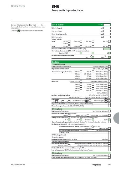
Order form SM6<br />
Fuse switch protection<br />
Only one of the boxes (ticked X or fi lled by<br />
the needed value) have to be considered between each<br />
horizontal line.<br />
Green box X corresponds to none priced functions.<br />
AMTED398078EN.indd<br />
Basic cubicle<br />
Quantity<br />
Rated voltage Ur (kV)<br />
Service voltage (kV)<br />
Short-circuit current Isc (kA)<br />
Rated current Ir (A)<br />
Type of cubicle<br />
24 kV QM 375 QMB 375 QMC 625 PM 375<br />
QM 500<br />
36 kV QM 750 QMB 750 QMC 1000 PM 750<br />
Position number in the switchboard (from left to right)<br />
Current transformers for QMC 24 kV (to see price structure)<br />
Quantity of CTs 1 2 3<br />
Direction of lower busbars for QMB<br />
Left Right<br />
Options<br />
Common options<br />
Fuses (see fuse price structure) Service voltage y 12 kV<br />
Replacement of mechanism CIT by CI1 (only for PM)<br />
Electrical driving motorization 24 Vdc 110 Vdc 120/127 Vac (50 Hz)<br />
32 Vdc 120-125 Vdc 220/230 Vac (50 Hz)<br />
48 Vdc 137 Vdc 120/127 Vac (60 Hz)<br />
60 Vdc 220 Vdc 220/230 Vac (60 Hz)<br />
Shunt trip Opening (on CI1) Closing and opening (on CI2)<br />
24 Vdc 110 Vdc 120/127 Vac (50 Hz)<br />
32 Vdc 120-125 Vdc 220/230 Vac (50 Hz)<br />
48 Vdc 137 Vdc 120/127 Vac (60 Hz)<br />
60 Vdc 220 Vdc 220/230 Vac (60 Hz)<br />
380 Vac (50/60 Hz)<br />
Auxiliary contact signalling 1 C on SW and 1 O & 1 C on ES<br />
Interlocking<br />
A1 C1 C4<br />
2 O & 2 C on SW 2 O & 3 C on SW and 1 O & 1 C on ES<br />
Standard key type Round key type<br />
Replacement of 630 A upper busbar by 1250 A (not possible for QMB)<br />
Blown fuse signalling contact (for QM, QMB, QMC)<br />
24 kV options<br />
Replacement of mechanism CI1 by CI2 (only for QM)<br />
Remote control signalling (for QM only)<br />
2 lights 2 lights and 2 PB 2 lights and 2 PB + 1 switch<br />
Voltage of the lights (must be the same than electrical driving mechanism)<br />
24 V 48 V 110/125 V 220 V<br />
Blown fuse signalling contact (mechanical indication PM, electrical for the other cubicles)<br />
Roof confi guration (A, B or C only one choice possible)<br />
A - Cable connection by the top (cable maxi 240 mm2 with VPIS)<br />
Single core 2 x single core<br />
B - Low voltage control cabinet (h = 450 mm) With unpunched door<br />
C - Wiring duct<br />
50 W heating element<br />
Operation counter<br />
Digital ammeter (not applicable for QMB) AMP21D<br />
Visibility of main contacts<br />
Pressure indicator device Analogic manometer without visibility of main contacts<br />
Pressure switch Analogic manometer with visibility of main contacts<br />
Field distributor for severe conditions (only for 630 A)<br />
Internal arc version 16 kA 1 s (not possible with “top incomer” option)<br />
36 kV options<br />
Replacement of mechanism CIT by CI2 (only for PM)<br />
Cable connection by the top (single core cable maxi 240 mm 2 with VPIS)<br />
105

![Data Center Solutions [EN011] ZPAS - SLO Latvia](https://img.yumpu.com/15723906/1/185x260/data-center-solutions-en011-zpas-slo-latvia.jpg?quality=85)