Modular units
Modular units
Modular units

You also want an ePaper? Increase the reach of your titles
YUMPU automatically turns print PDFs into web optimized ePapers that Google loves.
DE53595<br />
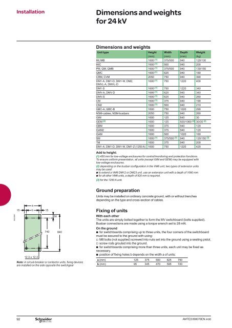
Installation Dimensions and weights<br />
for 24 kV<br />
15<br />
a<br />
b 15<br />
50<br />
740 840<br />
12.3 x 12.3<br />
Note: in circuit-breaker or contactor <strong>units</strong>, fi xing devices<br />
are installed on the side opposite the switchgear<br />
Dimensions and weights<br />
Unit type Height Width Depth Weight<br />
(mm) (mm) (mm) (kg)<br />
IM,IMB 1600 (1) 375/500 940 120/130<br />
IMC 1600 (1) 500 940 200<br />
PM, QM, QMB 1600 (1) 375/500 940 130/150<br />
QMC 1600 (1) 625 940 180<br />
CRM, CVM 2050 750 940 390<br />
DM1-A, DM1-D, DM1-W, DM2,<br />
DMVL-A, DMVL-D<br />
1600 (1) 750 1220 400<br />
DM1-S 1600 (1) 750 1220 340<br />
DMV-A, DMV-D 1695 (1) 625 940 340<br />
DMV-S 1600 (1) 625 940 260<br />
CM 1600 (1) 375 940 190<br />
CM2 1600 (1) 500 940 210<br />
GBC-A, GBC-B 1600 750 1020 290<br />
NSM-cables, NSM-busbars 2050 750 940 260<br />
GIM 1600 125 840 30<br />
GEM (2) 1600 125 920/1060 (2) 30/35 (2)<br />
GBM 1600 375 940 120<br />
GAM2 1600 375 940 120<br />
GAM 1600 500 1020 160<br />
SM 1600 (1) 375/500 (3) 940 120/150 (3)<br />
TM 1600 375 940 200<br />
DM1-A, DM1-D, DM1-W, DM1-Z (1250 A) 1600 750 1220 420<br />
Add to height:<br />
(1) 450 mm for low-voltage enclosures for control/monitoring and protection functions.<br />
To ensure uniform presentation, all <strong>units</strong> (except GIM and GEM) may be equipped with<br />
low-voltage enclosures.<br />
(2) depending on the busbar confi guration in the VM6 unit, two types of extension <strong>units</strong><br />
may be used:<br />
b to extend a VM6 DM12 or DM23 unit, use an extension unit with a depth of 1060 mm<br />
b for all other VM6 <strong>units</strong>, a depth of 920 mm is required.<br />
(3) for the 1250 A unit.<br />
Ground preparation<br />
Units may be installed on ordinary concrete ground, with or without trenches<br />
depending on the type and cross-section of cables.<br />
Fixing of <strong>units</strong><br />
With each other<br />
The <strong>units</strong> are simply bolted together to form the MV switchboard (bolts supplied).<br />
Busbar connections are made using a torque wrench set to 28 mN.<br />
On the ground<br />
b for switchboards comprising up to three <strong>units</strong>, the four corners of the switchboard<br />
must be secured to the ground with using:<br />
v M8 bolts (not supplied) screwed into nuts set into the ground using a sealing pistol,<br />
v screw rods grouted into the ground.<br />
b for switchboards comprising more than three <strong>units</strong>, each unit may be fi xed as<br />
necessary.<br />
b position of fi xing holes b depends on the width a of <strong>units</strong>:<br />
a (mm) 125 375 500 625 750<br />
b (mm) 95 345 470 595 720<br />
92 AMTED398078EN.indd


![Data Center Solutions [EN011] ZPAS - SLO Latvia](https://img.yumpu.com/15723906/1/185x260/data-center-solutions-en011-zpas-slo-latvia.jpg?quality=85)