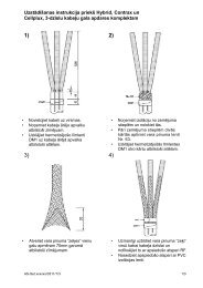
Modular units
Modular units
Modular units

Create successful ePaper yourself
Turn your PDF publications into a flip-book with our unique Google optimized e-Paper software.
DE58409<br />
PE50797<br />
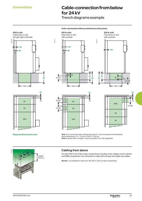
Connections Cable-connection from below<br />
for 24 kV<br />
Trench diagrams example<br />
630 A <strong>units</strong><br />
Cable entry or exit<br />
through right or left side<br />
140<br />
80<br />
600<br />
IM<br />
IM<br />
DM1<br />
AMTED398078EN.indd<br />
22<br />
70<br />
P2<br />
DE58410<br />
Units represented without switchboard side panels<br />
630 A <strong>units</strong><br />
Rear entry or exit<br />
with conduits<br />
140<br />
80<br />
IM<br />
IM<br />
DM1<br />
P1 P2<br />
22<br />
DE58411<br />
P1<br />
P3<br />
630 A <strong>units</strong><br />
Front entry or exit<br />
with conduits<br />
Required dimensions (mm) Note 1: for connection with conduits, the bevel (C) must correspond to the following<br />
trench dimensions: P1 = 75 mm or P2/P3 = 150 mm.<br />
Note 2: please refer to chapter “Layout examples” for a site application.<br />
Height:<br />
450 mm<br />
Cabling from above<br />
140<br />
QMC<br />
On each 630 A unit of the range, except those including a low-voltage control cabinet<br />
and EMB compartment, the connection is made with dry-type and single-core cables.<br />
Remark : not available for internal arc IEC 62271-200 in busbar compartment.<br />
IM<br />
IM<br />
87<br />
22


![Data Center Solutions [EN011] ZPAS - SLO Latvia](https://img.yumpu.com/15723906/1/185x260/data-center-solutions-en011-zpas-slo-latvia.jpg?quality=85)