Back Room Front Room 2
Back Room Front Room 2
Back Room Front Room 2
Create successful ePaper yourself
Turn your PDF publications into a flip-book with our unique Google optimized e-Paper software.
174 ENTERPRISE INFORMATION SYSTEMS VI<br />
All notions mentioned above are well defined based<br />
on partial ordered run of the workflow module (see<br />
(Martens, 2004)). Because of the limited space, we do<br />
not go into further details. Applying these notions, we<br />
are now able to present the construction of the communication<br />
graph. The algorithm starts with the root<br />
node v0 labeled with the initial state:<br />
1. For each state within the label of vi calculate the<br />
set of activated inputs: �<br />
z∈m(vi) INP(z).<br />
2. For each activated input i within this set:<br />
(a) Add a new hidden node h, add a new edge<br />
(vi,h) with the label i.<br />
(b) For each state within the label of vi calculate the<br />
set of possible outputs: �<br />
z∈m(vi) OUT(z + i).<br />
(c) For each possible output o within this set:<br />
i. Add a new visible node vi+1, add a new edge<br />
(h,vi+1) with the label o.<br />
ii. For each state z ∈ m(vi) and for each communication<br />
step (z,i,o,z ′ ) ∈S(M) add z ′ to the<br />
label of vi+1.<br />
iii. If there exists a visible node vj such that<br />
m(vi+1) = m(vj) then merge vj and vi+1.<br />
Otherwise, goto step 1 with node vi+1.<br />
The communication graph of a module contains that<br />
information, a “good natured” environment can derive.<br />
That means, the environment always sends as<br />
little messages as possible, but as much as necessary<br />
to achieve an answer resp. to terminate the process in<br />
a proper state. By considering all reachable successor<br />
states together with all possible outputs, the choices<br />
within the module are not restricted.<br />
3.3<br />
The Usability Graph<br />
By help of the communication graph we can decide<br />
the usability of a module. A communication graph<br />
may have several leaf nodes: none, finitely or infinitely<br />
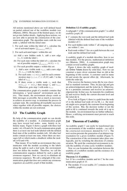
many. Figure 4 shows a graph with three leaf<br />
nodes: v4, v13 and v14. In each communication graph<br />
there is at most one leaf node labeled with the defined<br />
final state of the workflow module (v4). All other leaf<br />
nodes contain at least one state, where there are messages<br />
left or which marks a deadlock within the module<br />
(v13 and v14).<br />
That means: If we build an environment that communicates<br />
with the module according to the labels<br />
along the path to such a leaf node, this environment<br />
does not utilize the module. Therefore, we call the<br />
communication sequence defined by such a path an<br />
erroneous sequence. Now we can try to eliminate all<br />
erroneous sequences. We call a subgraph of the communication<br />
graph that does not contain any erroneous<br />
sequences an usability graph of that module.<br />
Definition 3.2 (Usability graph).<br />
A subgraph U of the communication graph C is called<br />
usability graph, iff<br />
• U contains the root node and the defined leaf node<br />
(labeled with the defined final state of the workflow<br />
module) of C.<br />
• For each hidden node within U all outgoing edges<br />
are within U, too.<br />
• Each node within U lies on a path between the root<br />
node and the defined leaf node. ⋆<br />
A usability graph of a module describes, how to use<br />
that module. For the precise, mathematical definition<br />
see (Martens, 2004). A communication graph may<br />
contain several usability graphs.<br />
Figure 4 shows the only usability graph of module<br />
Online Tickets drawn by solid lines. Now we can<br />
construct a more clever customer than we did at the<br />
beginning of this section: A customer send its name<br />
[n] and awaits the special offers [s]. Afterwards, he<br />
sends the order [o].<br />
If he receives the business terms [b], he was classified<br />
as standard customer. Thus, he pays [p] and gets<br />
an acknowledgement and the ticket [a, t]. Otherwise,<br />
he is a premium customer and receives an acknowledgement<br />
[a]. In that case, he transmits his conditions<br />
[c] and receives finally the current discount level and<br />
the ticket [d, t].<br />
If we look at Figure 4, there is a path from the node<br />
v1 to the defined leaf node v4 via h5, i. e. the module<br />
might serve properly the customer from beginning<br />
of this section. But, the decision wether or not the<br />
path to h5 is continued towards the node v4 is up to<br />
the module. An environment has no further influence.<br />
Hence, a utilizing environment must prevent to reach<br />
this node.<br />
3.4<br />
Theorem of Usability<br />
An usability graph U can easily be transformed into<br />
an environment of the workflow module – we call it<br />
the constructed environment, denoted by Γ(U). The<br />
next section presents the generation of an abstract representation<br />
for a given workflow module (Figure 5).<br />
The construction of the environment takes place analogically,<br />
just by switching the directions of communication.<br />
We need the constructed environment to decide<br />
the usability of some cyclic workflow modules.<br />
Now we can formulate the correlation between the<br />
usability of a workflow module and the existence of a<br />
usability graph:<br />
Theorem 3.1 (Usability).<br />
Let M be a workflow module and let C be the communication<br />
graph of M.<br />
• The module M is not usable, if C contains no finite<br />
usability graph.


