Back Room Front Room 2
Back Room Front Room 2
Back Room Front Room 2

Create successful ePaper yourself
Turn your PDF publications into a flip-book with our unique Google optimized e-Paper software.
224 ENTERPRISE INFORMATION SYSTEMS VI<br />
(3) DFD DFD ′ 1 2 1 1 EDGE 1 1 Node<br />
: (DFD1 =DFD ′<br />
1− EDGE2)<br />
: (PLACEHOLD; Node1 1; PLACEHOLD1 = Node1− EDGE1)<br />
(4) DFD DFD ′ any PLACEHOLD<br />
: (DFD1 =DFD ′<br />
1 +PLACEHOLD1)<br />
(5) Node STORE<br />
: (Node1 =STORE1)<br />
(6) Node PROCESS<br />
: (Node1 = PROCESS1)<br />
(7) Node ENTITY<br />
: (Node1 = ENTITY1)<br />
(8) Node PLACEHOLD<br />
: (Node1 = PLACEHOLD1)<br />
According to these rules, a data flow diagram is defined<br />
as<br />
• a Node (production 1) or, recursively, as<br />
• a DFD connected to a node through an outgoing<br />
(production 2) or incoming (production 3) edge.<br />
A Node can be either a data store node (production<br />
5), or a processing step node (production 6), an entity<br />
(production 7).<br />
Let us observe that the relation identifier any denotes<br />
a relation that is always satisfied between any<br />
pair of symbols. PLACEHOLD is a fictitious terminal<br />
symbol to be dynamically inserted in the input sentence<br />
during the parsing process. It has one attaching<br />
region as syntactic attribute. Moreover, notice that<br />
DFD1 = DFD ′ 1 EDGE1 indicates set difference and<br />
has to be interpreted as follows: “the attaching area 1<br />
of DFD has to be connected to whatever is attached<br />
to the attaching area 1 of DFD ′ except for the attaching<br />
point 1 of EDGE”. Moreover the notation |Node1|<br />
indicates the number of connections to the attaching<br />
area 1 of Node.<br />
Now, by adding semantic rules to the XPG productions<br />
it is possible to translate any DFD sentence into<br />
the corresponding GXL instance in agreement with<br />
the data flow diagram GXL schema.<br />
It is worth noting that the verification of properties<br />
of visual languages can be carried out during a static<br />
semantic analysis by exploiting the syntax structure<br />
given in output by the syntactic analysis. To this aim,<br />
semantic attributes and semantic rules can be added to<br />
the symbols and to the productions of the XPG specification<br />
in order to obtain a syntax structure summarizing<br />
the information of the input visual sentence.<br />
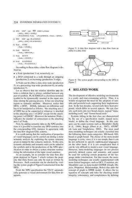
As an example, let us consider the data flow diagram<br />
depicted in Figure 7 which violates the property<br />
that Data Stores can only be read or written by<br />
Processes. Such constraint can be checked by visiting<br />
the syntax graph of Figure 8 constructed from the<br />
DFD.<br />
From the XPG specification the VLCC automatically<br />
generates a visual environment for data flow diagrams.<br />
CUSTOMER<br />
customer order<br />
receipt<br />
FOOD<br />
ORDER<br />
food order<br />
food order receipt<br />
RECEIPT<br />
order receipt<br />
KITCHEN<br />
Figure 7: A data flow diagram with a data flow from an<br />
entity to a data store<br />
ROOT<br />
Customer kitchen<br />
Food<br />
Order receipt<br />
Figure 8: The syntax graph corresponding to the DFD in<br />
Figure 7<br />
4 RELATED WORK<br />
The development of effective modeling environments<br />
is a costly and time-consuming activity. Thus, it is<br />
widely recognized the need for the adoption of suitable<br />
and powerful tools supporting their implementation.<br />
In the last decades, several tools have been proposed,<br />
which differ in several aspects. We can classify<br />
such tools into two broad classes, named “metamodeling<br />
tools” and “formal-based tools”.<br />
Systems falling in the first class are characterized<br />
by the use of a specification model, named metamodel,<br />
to define the visual language. In this category<br />
can be count systems such as MetaEdit+ (Kelly<br />
et al., 1996), Kogge (Ebert et al., 1997), ATOM 3<br />
(de Lara and Vangheluwe, 2002). The most used<br />
meta-modeling techniques are usually classified into<br />
the following three main categories: ER-based, OObased<br />
or graph based. The choice of the meta-model<br />
language is critic, since if it is too simple then it can<br />
be not sufficient to specify sophisticated languages;<br />
on the other hand, if it is too complicated then it<br />
can be very difficult to model a new visual language.<br />
However, meta-modeling languages do not possess<br />
precisely defined syntax and semantic, and cannot<br />
be used for verifying certain properties of the language<br />
under construction. For that reason, the metamodeling<br />
techniques are usually supplemented with<br />
more formal languages, such as OCL, Z notation, etc.<br />
MetaEdit+ uses as meta-model GOPRR (Graph, Objects,<br />
Properties, Relationships, Roles) that adds the<br />
concept of graph to OPRR model. It allows the integration<br />
of concepts and rules for checking model<br />
integrity, consistency, and completeness by defining