Journal of Mechanics of Materials and Structures vol. 5 (2010 ... - MSP
Journal of Mechanics of Materials and Structures vol. 5 (2010 ... - MSP
Journal of Mechanics of Materials and Structures vol. 5 (2010 ... - MSP

Create successful ePaper yourself
Turn your PDF publications into a flip-book with our unique Google optimized e-Paper software.
848 ANDREY V. PYATIGORETS, MIHAI O. MARASTEANU, LEV KHAZANOVICH AND HENRYK K. STOLARSKI<br />
transform with the numerical solution found by the present approach for n = 2500. As in the previous<br />
problem, the results from the both methods match very well. The stress rises linearly in this case due to<br />
the use <strong>of</strong> modified shift factor âT (T ), which depends linearly on temperature.<br />
Simulation <strong>of</strong> thermal stresses in Asphalt Binder Cracking Device. This section is devoted to the study<br />
<strong>of</strong> viscoelastic fields e<strong>vol</strong>ution in specimens undergoing thermal loading in the Asphalt Binder Cracking<br />
Device (ABCD). ABCD was developed in [Kim 2005; Kim et al. 2006] for direct measurements <strong>of</strong><br />
cracking temperature <strong>of</strong> asphalt binders. Based on the present approach, it is possible to relate measured<br />
strains to time-dependent thermal stresses that cause the cracking <strong>of</strong> the binder <strong>and</strong> determine its strength<br />
at the cracking temperature.<br />
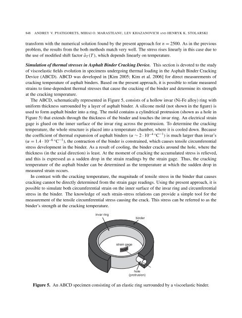
The ABCD, schematically represented in Figure 5, consists <strong>of</strong> a hollow invar (Ni-Fe alloy) ring with<br />
uniform thickness surrounded by a layer <strong>of</strong> asphalt binder. A silicone mold (not shown in the figure) is<br />
used to form asphalt binder into a ring. The mold contains a cylindrical protrusion (shown as a hole in<br />
Figure 5) that extends through the thickness <strong>of</strong> the binder <strong>and</strong> touches the invar ring. An electrical strain<br />
gage is glued on the inner surface <strong>of</strong> the invar ring across the protrusion. To determine the cracking<br />
temperature, the whole structure is placed into a temperature chamber, where it is cooled down. Because<br />
the coefficient <strong>of</strong> thermal expansion <strong>of</strong> asphalt binders (α ∼ 2 · 10 −4 ◦ C −1 ) is much larger than invar’s<br />
(α = 1.4 · 10 −6 ◦ C −1 ), the contraction <strong>of</strong> the binder is constrained, which causes tensile circumferential<br />
stress development in the binder. As a result <strong>of</strong> cooling, the binder cracks around the hole, where the<br />
thickness (in the axial direction) is least. At the moment <strong>of</strong> cracking the accumulated stress is relieved,<br />
<strong>and</strong> this is expressed as a sudden drop in the strain readings by the strain gage. Thus, the cracking<br />
temperature <strong>of</strong> the asphalt binder can be determined as the temperature at which the sudden drop in<br />
measured strain occurs.<br />
In contrast with the cracking temperature, the magnitude <strong>of</strong> tensile stress in the binder that causes<br />
cracking cannot be directly determined from the strain gage readings. Using the present approach, it is<br />
possible to simulate both circumferential strain on the inner surface <strong>of</strong> the invar ring <strong>and</strong> circumferential<br />
stress in the binder. The knowledge <strong>of</strong> such strain-stress relations can provide a simple tool for the<br />
measurement <strong>of</strong> the tensile circumferential stress causing the crack. This stress can be referred to as the<br />
binder’s strength at the cracking temperature.<br />
Figure 5. An ABCD specimen consisting <strong>of</strong> an elastic ring surrounded by a viscoelastic binder.