Journal of Mechanics of Materials and Structures vol. 5 (2010 ... - MSP
Journal of Mechanics of Materials and Structures vol. 5 (2010 ... - MSP
Journal of Mechanics of Materials and Structures vol. 5 (2010 ... - MSP

Create successful ePaper yourself
Turn your PDF publications into a flip-book with our unique Google optimized e-Paper software.
726 BAHATTIN KILIC AND ERDOGAN MADENCI<br />
where � + <strong>and</strong> � − are the <strong>vol</strong>umes in which integration is performed <strong>and</strong> are defined to be the right <strong>and</strong><br />
left sides <strong>of</strong> the x-plane (Figure A1). The subscript x indicates the x- component <strong>of</strong> the resulting <strong>vol</strong>ume<br />
integration. For a point, x embedded in a single material, the value <strong>of</strong> gx(x) will become 2.<br />
Moreover, by applying the displacement gradient in the y-direction, the force density, gy(x), can<br />
written as<br />
� �<br />
gy(x) =<br />
� +<br />
dV ′ f (u ′ , u, x ′ �<br />
, x) −<br />
�− dV ′ f (u ′ , u, x ′ �<br />
, x) , (A3)<br />
y<br />
where � + <strong>and</strong> � − are the <strong>vol</strong>umes in which integration is performed; they are defined to be the upper<br />
<strong>and</strong> lower sides <strong>of</strong> the y-plane (Figure A1). The force densities, gx(x) <strong>and</strong> gy(x), are clearly different<br />
due to dissimilar <strong>vol</strong>umes <strong>of</strong> integrations. Hence, the domain under uniaxial tension exhibits directional<br />
dependence. In other words, depending on the direction <strong>of</strong> uniaxial tension, the points closer to the free<br />
surfaces or interfaces experience different force densities, which is not physically acceptable. Therefore,<br />
the uniaxial tension is also applied in the y- <strong>and</strong> z-directions, which leads to three different responses at<br />
each integration point <strong>and</strong> can be expressed in vector form<br />
g T (x) = � �<br />
gx gy gz , (A4)<br />
in which x, y, <strong>and</strong> z represent the directions <strong>of</strong> applied uniaxial tension.<br />
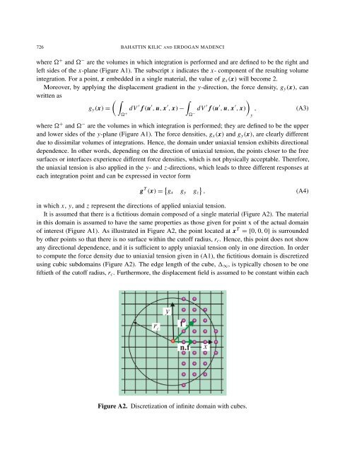
It is assumed that there is a fictitious domain composed <strong>of</strong> a single material (Figure A2). The material<br />
in this domain is assumed to have the same properties as those given for point x <strong>of</strong> the actual domain<br />
<strong>of</strong> interest (Figure A1). As illustrated in Figure A2, the point located at x T = {0, 0, 0} is surrounded<br />
by other points so that there is no surface within the cut<strong>of</strong>f radius, rc. Hence, this point does not show<br />
any directional dependence, <strong>and</strong> it is sufficient to apply uniaxial tension only in one direction. In order<br />
to compute the force density due to uniaxial tension given in (A1), the fictitious domain is discretized<br />
using cubic subdomains (Figure A2). The edge length <strong>of</strong> the cube, �∞, is typically chosen to be one<br />
fiftieth <strong>of</strong> the cut<strong>of</strong>f radius, rc. Furthermore, the displacement field is assumed to be constant within each<br />
Figure A2. Discretization <strong>of</strong> infinite domain with cubes.