Journal of Mechanics of Materials and Structures vol. 5 (2010 ... - MSP
Journal of Mechanics of Materials and Structures vol. 5 (2010 ... - MSP
Journal of Mechanics of Materials and Structures vol. 5 (2010 ... - MSP
Create successful ePaper yourself
Turn your PDF publications into a flip-book with our unique Google optimized e-Paper software.
764 XIAO-TING HE, QIANG CHEN, JUN-YI SUN, ZHOU-LIAN ZHENG AND SHAN-LIN CHEN<br />
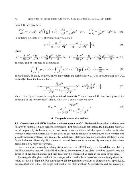
From (30), we may have<br />
∂2w ∂x 2 = 4C1(3x 2 − a 2 �� �<br />
y 2 �<br />
) + 1 ,<br />
4b<br />
∂2w C1<br />
=<br />
∂y 2 8b2 (x2 − a 2 ) 2 ,<br />
∂2w C1<br />
=<br />
∂x∂y 2b2 (x3 − a 2 x)y. (35)<br />
Substituting (35) into (34), after integrating we obtain<br />
�<br />
E<br />
U =<br />
+ t3 1<br />
6[1 − (µ + ) 2 ] F+ E<br />
+<br />
−t 3 2<br />
6[1 − (µ − ) 2 ] F−<br />
�<br />
C 2 1 , (36)<br />
where<br />
F + = 8 a<br />
315<br />
9 �<br />
16<br />
+<br />
b3 315 −µ+ 136<br />
105<br />
� a 7<br />
The right end <strong>of</strong> (31) may be computed as<br />
� a � b<br />
−a<br />
b<br />
qwm dx dy =<br />
−b<br />
4003<br />
+<br />
75 a5b, F − = 8 a<br />
315<br />
9 �<br />
16<br />
+<br />
b3 315 −µ− 136<br />
105<br />
� a � b<br />
−a<br />
−b<br />
� a 7<br />
b<br />
+ 4003<br />
75 a5 b. (37)<br />
q(x 2 − a 2 ) 2�� �<br />
y 2 �<br />
+ 1 dx dy =<br />
4b<br />
98<br />
45 qa5b. (38)<br />
Substituting (36) <strong>and</strong> (38) into (31), we may obtain the formula for C1. After substituting it into (30),<br />
we finally obtain the formula for w:<br />
w =<br />
98<br />
15 qa5 b<br />
E + t3 1<br />
1 − (µ + ) 2 F+ + E−t 3 2<br />
1 − (µ − F−<br />
) 2<br />
(x 2 − a 2 ) 2�� �<br />
y 2 �<br />
+ 1 , (39)<br />
4b<br />
where t1 <strong>and</strong> t2 are known <strong>and</strong> may be obtained from (14). The maximum deflection takes place at the<br />
midpoints <strong>of</strong> the two free sides, that is, while x = 0 <strong>and</strong> y = ±b, we have<br />
wmax =<br />
833<br />
120 qa9 b<br />
E + t3 1<br />
1 − (µ + ) 2 F+ + E−t 3 2<br />
1 − (µ − F−<br />
) 2<br />
4. Comparisons <strong>and</strong> discussions<br />
. (40)<br />
4.1. Comparisons with FEM based on Ambartsumyan’s model. The bimodular problem attributes nonlinearity<br />
to materials. Since existent commercial FEM programs do not include the bimodular materials<br />
model proposed by Ambartsumyan, it is necessary to work out a numerical program based on an iterative<br />
technique. Because the stress state <strong>of</strong> the point in question is unknown in advance, we have to begin with<br />
a single modulus problem, thus gaining the initial stress state to form a corresponding elasticity matrix<br />
for each element. Generally, direct iterative methods based on an incrementally e<strong>vol</strong>ving stiffness have<br />
been adopted by many researchers.<br />
Based on an incrementally e<strong>vol</strong>ving stiffness, Gao et al. [1998] analyzed a bimodular thin plate by<br />
the direct iterative method. In the FEM analysis, the elements <strong>of</strong> the plate should be layered along the<br />
direction <strong>of</strong> the plate thickness <strong>and</strong> each layer may be considered as being in the same stress state.<br />
A rectangular thin plate fixed at its two longer sides is under the action <strong>of</strong> normal uniformly-distributed<br />
loads, as shown in Figure 5. For convenience, all the quantities are taken as dimensionless, specifically,<br />
the plate thickness is 0.24, the length <strong>and</strong> width <strong>of</strong> the plate are 8 <strong>and</strong> 6, respectively, <strong>and</strong> the intensity <strong>of</strong>


