Journal of Mechanics of Materials and Structures vol. 5 (2010 ... - MSP
Journal of Mechanics of Materials and Structures vol. 5 (2010 ... - MSP
Journal of Mechanics of Materials and Structures vol. 5 (2010 ... - MSP

Create successful ePaper yourself
Turn your PDF publications into a flip-book with our unique Google optimized e-Paper software.
722 BAHATTIN KILIC AND ERDOGAN MADENCI<br />
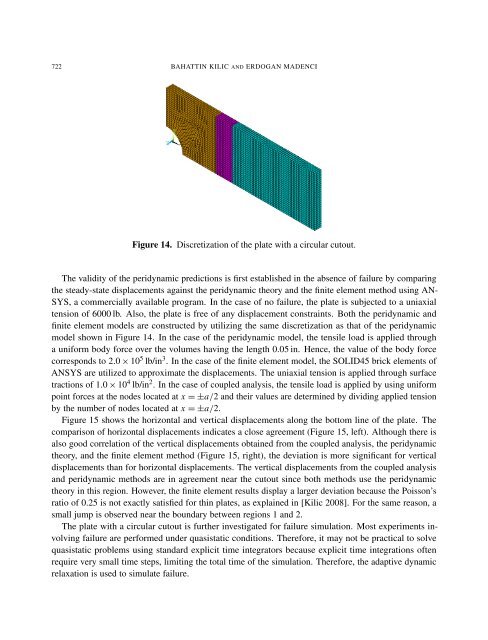
Figure 14. Discretization <strong>of</strong> the plate with a circular cutout.<br />
The validity <strong>of</strong> the peridynamic predictions is first established in the absence <strong>of</strong> failure by comparing<br />
the steady-state displacements against the peridynamic theory <strong>and</strong> the finite element method using AN-<br />
SYS, a commercially available program. In the case <strong>of</strong> no failure, the plate is subjected to a uniaxial<br />
tension <strong>of</strong> 6000 lb. Also, the plate is free <strong>of</strong> any displacement constraints. Both the peridynamic <strong>and</strong><br />
finite element models are constructed by utilizing the same discretization as that <strong>of</strong> the peridynamic<br />
model shown in Figure 14. In the case <strong>of</strong> the peridynamic model, the tensile load is applied through<br />
a uniform body force over the <strong>vol</strong>umes having the length 0.05 in. Hence, the value <strong>of</strong> the body force<br />
corresponds to 2.0 × 10 5 lb/in 3 . In the case <strong>of</strong> the finite element model, the SOLID45 brick elements <strong>of</strong><br />
ANSYS are utilized to approximate the displacements. The uniaxial tension is applied through surface<br />
tractions <strong>of</strong> 1.0 × 10 4 lb/in 2 . In the case <strong>of</strong> coupled analysis, the tensile load is applied by using uniform<br />
point forces at the nodes located at x = ±a/2 <strong>and</strong> their values are determined by dividing applied tension<br />
by the number <strong>of</strong> nodes located at x = ±a/2.<br />
Figure 15 shows the horizontal <strong>and</strong> vertical displacements along the bottom line <strong>of</strong> the plate. The<br />
comparison <strong>of</strong> horizontal displacements indicates a close agreement (Figure 15, left). Although there is<br />
also good correlation <strong>of</strong> the vertical displacements obtained from the coupled analysis, the peridynamic<br />
theory, <strong>and</strong> the finite element method (Figure 15, right), the deviation is more significant for vertical<br />
displacements than for horizontal displacements. The vertical displacements from the coupled analysis<br />
<strong>and</strong> peridynamic methods are in agreement near the cutout since both methods use the peridynamic<br />
theory in this region. However, the finite element results display a larger deviation because the Poisson’s<br />
ratio <strong>of</strong> 0.25 is not exactly satisfied for thin plates, as explained in [Kilic 2008]. For the same reason, a<br />
small jump is observed near the boundary between regions 1 <strong>and</strong> 2.<br />
The plate with a circular cutout is further investigated for failure simulation. Most experiments in<strong>vol</strong>ving<br />
failure are performed under quasistatic conditions. Therefore, it may not be practical to solve<br />
quasistatic problems using st<strong>and</strong>ard explicit time integrators because explicit time integrations <strong>of</strong>ten<br />
require very small time steps, limiting the total time <strong>of</strong> the simulation. Therefore, the adaptive dynamic<br />
relaxation is used to simulate failure.