Journal of Mechanics of Materials and Structures vol. 5 (2010 ... - MSP
Journal of Mechanics of Materials and Structures vol. 5 (2010 ... - MSP
Journal of Mechanics of Materials and Structures vol. 5 (2010 ... - MSP

You also want an ePaper? Increase the reach of your titles
YUMPU automatically turns print PDFs into web optimized ePapers that Google loves.
850 ANDREY V. PYATIGORETS, MIHAI O. MARASTEANU, LEV KHAZANOVICH AND HENRYK K. STOLARSKI<br />
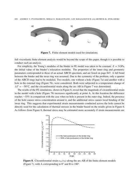
Figure 7. Finite element models used for simulations.<br />
full viscoelastic finite element analysis would be beyond the scope <strong>of</strong> this paper, though it is possible to<br />
conduct such an analysis.<br />
For simplicity, the Young’s modulus <strong>of</strong> the binder in FE model was taken to be constant: E = 3 GPa,<br />
the initial value <strong>of</strong> the binder’s relaxation modulus. The properties <strong>of</strong> the inner ring <strong>and</strong> geometric<br />
parameters corresponded to those <strong>of</strong> an actual ABCD specimen, <strong>and</strong> are listed on page 847. A full bond<br />
between the binder <strong>and</strong> the invar ring was assumed. Due to the symmetry <strong>of</strong> the problem, only a quarter<br />
<strong>of</strong> the ABCD rings had to be modeled. Two models, one without a hole (Figure 7a) <strong>and</strong> another with a<br />
hole in the external ring (Figure 7b), were considered. Both were subjected to a temperature change <strong>of</strong><br />
�T = −50 ◦ C, <strong>and</strong> the circumferential strain along the arc AB in Figure 7 was determined.<br />
The results <strong>of</strong> the FE simulations, shown in Figure 8, reveal that the magnitude <strong>of</strong> circumferential strain<br />
in the model with a hole (Figure 7b) increases significantly at point A. At this location the difference<br />
reaches ∼55% in comparison with the case when no hole is present in the outer ring. Indeed, the presence<br />
<strong>of</strong> the hole causes stress concentration around it, <strong>and</strong> the additional stress causes local bending <strong>of</strong> the<br />
invar ring. This suggests that experimental strain measurements conducted across the hole cannot be<br />
directly used for the calculation <strong>of</strong> thermal stresses in the binder based on the results given in Figure 6.<br />
As follows from Figure 8, thermal stress may be estimated more accurately if strain measurements are<br />
����������������������� �� � ������ ��<br />
����<br />
����<br />
����<br />
����<br />
����<br />
����<br />
����<br />
����<br />
����<br />
����������������������������������������<br />
��������������������������������������������<br />
� �� �� �� �� ��� ��� ��� ��� ���<br />
�����<br />
Figure 8. Circumferential strain εθθ(r0) along the arc AB <strong>of</strong> the finite element models<br />
(Figure 7), with A corresponding to 0 ◦ <strong>and</strong> B to 180 ◦ .