Journal of Mechanics of Materials and Structures vol. 5 (2010 ... - MSP
Journal of Mechanics of Materials and Structures vol. 5 (2010 ... - MSP
Journal of Mechanics of Materials and Structures vol. 5 (2010 ... - MSP

You also want an ePaper? Increase the reach of your titles
YUMPU automatically turns print PDFs into web optimized ePapers that Google loves.
COUPLING OF PERIDYNAMIC THEORY AND THE FINITE ELEMENT METHOD 723<br />
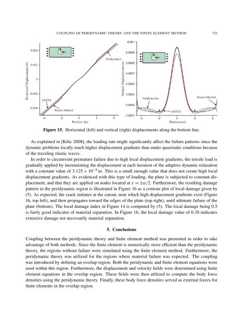
Figure 15. Horizontal (left) <strong>and</strong> vertical (right) displacements along the bottom line.<br />
As explained in [Kilic 2008], the loading rate might significantly affect the failure patterns since the<br />
dynamic problems locally reach higher displacement gradients than under quasistatic conditions because<br />
<strong>of</strong> the traveling elastic waves.<br />
In order to circumvent premature failure due to high local displacement gradients, the tensile load is<br />
gradually applied by incrementing the displacement at each iteration <strong>of</strong> the adaptive dynamic relaxation<br />
with a constant value <strong>of</strong> 3.125 × 10 −8 in. This is a small enough value that does not create high local<br />
displacement gradients. As evidenced with this type <strong>of</strong> loading, the plate is subjected to constant displacement,<br />
<strong>and</strong> that they are applied on nodes located at x = ±a/2. Furthermore, the resulting damage<br />
pattern in the peridynamic region is illustrated in Figure 16 as a contour plot <strong>of</strong> local damage given by<br />
(5). As expected, the crack initiates at the cutout, near which high displacement gradients exist (Figure<br />
16, top left), <strong>and</strong> then propagates toward the edges <strong>of</strong> the plate (top right), until ultimate failure <strong>of</strong> the<br />
plate (bottom). The local damage index in Figure 14 is computed by (5). The local damage being 0.5<br />
is fairly good indicator <strong>of</strong> material separation. In Figure 16, the local damage value <strong>of</strong> 0.38 indicates<br />
extensive damage not necessarily material separation.<br />
5. Conclusions<br />
Coupling between the peridynamic theory <strong>and</strong> finite element method was presented in order to take<br />
advantage <strong>of</strong> both methods. Since the finite element is numerically more efficient than the peridynamic<br />
theory, the regions without failure were simulated using the finite element method. Furthermore, the<br />
peridynamic theory was utilized for the regions where material failure was expected. The coupling<br />
was introduced by defining an overlap region. Both the peridynamic <strong>and</strong> finite element equations were<br />
used within this region. Furthermore, the displacement <strong>and</strong> velocity fields were determined using finite<br />
element equations in the overlap region. These fields were then utilized to compute the body force<br />
densities using the peridynamic theory. Finally, these body force densities served as external forces for<br />
finite elements in the overlap region.