Journal of Mechanics of Materials and Structures vol. 5 (2010 ... - MSP
Journal of Mechanics of Materials and Structures vol. 5 (2010 ... - MSP
Journal of Mechanics of Materials and Structures vol. 5 (2010 ... - MSP

You also want an ePaper? Increase the reach of your titles
YUMPU automatically turns print PDFs into web optimized ePapers that Google loves.
COUPLING OF PERIDYNAMIC THEORY AND THE FINITE ELEMENT METHOD 725<br />
theory does not exactly satisfy its theoretical Poisson’s ratio <strong>of</strong> 0.25. In the case <strong>of</strong> the plate with the<br />
cutout, the steady-state results show trends similar to the bar problem when compared against predictions<br />
<strong>of</strong> the peridynamics <strong>and</strong> finite element methods. The failure simulation was also performed for a plate<br />
with a cutout. As expected, two cracks initiated at the cutout <strong>and</strong> they propagated with increasing tensile<br />
load until ultimate failure <strong>of</strong> the plate.<br />
Appendix A<br />
The correction factor is determined based on the application <strong>of</strong> uniaxial tensile loadings to the actual<br />
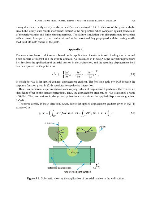
finite domain <strong>of</strong> interest <strong>and</strong> the infinite domain. As illustrated in Figure A1, the correction procedure<br />
first in<strong>vol</strong>ves the application <strong>of</strong> uniaxial tension in the x-direction, <strong>and</strong> the resulting displacement field<br />
can be expressed at the point x as<br />
u T �<br />
∂u ∗ ∂u∗ ∂u∗<br />
(x) = x −ν y −ν<br />
∂x ∂x ∂x z<br />
�T , (A1)<br />
in which ∂u ∗ /∂x is the applied constant displacement gradient. The Poisson’s ratio ν = 0.25 because the<br />
response function given in (2) is restricted to a pairwise interaction.<br />
Based on numerical experimentation with varying values <strong>of</strong> displacement gradients, there exists no<br />
significant effect on the surface corrections. Thus, the displacement gradient, ∂u ∗ /∂x is assigned a value<br />
<strong>of</strong> 0.001. The contractions in the y- <strong>and</strong> z-directions are ν times the applied displacement gradient,<br />
∂u ∗ /∂x.<br />
The force density in the x-direction, gx(x), due to the applied displacement gradient given in (A1) is<br />
expressed as<br />
� �<br />
gx(x) =<br />
� +<br />
dV ′ f (u ′ , u, x ′ �<br />
, x) −<br />
�− dV ′ f (u ′ , u, x ′ �<br />
, x) , (A2)<br />
x<br />
Figure A1. Schematic showing the application <strong>of</strong> uniaxial tension in the x-direction.