Journal of Mechanics of Materials and Structures vol. 5 (2010 ... - MSP
Journal of Mechanics of Materials and Structures vol. 5 (2010 ... - MSP
Journal of Mechanics of Materials and Structures vol. 5 (2010 ... - MSP

Create successful ePaper yourself
Turn your PDF publications into a flip-book with our unique Google optimized e-Paper software.
COUPLING OF PERIDYNAMIC THEORY AND THE FINITE ELEMENT METHOD 721<br />
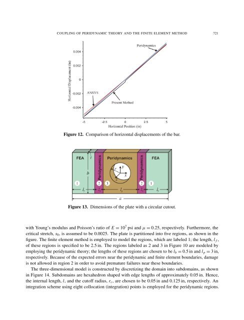
Figure 12. Comparison <strong>of</strong> horizontal displacements <strong>of</strong> the bar.<br />
Figure 13. Dimensions <strong>of</strong> the plate with a circular cutout.<br />
with Young’s modulus <strong>and</strong> Poisson’s ratio <strong>of</strong> E = 10 7 psi <strong>and</strong> µ = 0.25, respectively. Furthermore, the<br />
critical stretch, s0, is assumed to be 0.0025. The plate is partitioned into five regions, as shown in the<br />
figure. The finite element method is employed to model the regions, which are labeled 1; the length, l f ,<br />
<strong>of</strong> these regions is specified to be 2.5 in. The regions labeled as 2 <strong>and</strong> 3 in Figure 10 are modeled by<br />
employing the peridynamic theory; the lengths <strong>of</strong> these regions are chosen to be lb = 0.5 in <strong>and</strong> l p = 3 in,<br />
respectively. Because <strong>of</strong> the expected errors near the peridynamic <strong>and</strong> finite element boundaries, damage<br />
is not allowed in region 2 in order to avoid premature failures near these boundaries.<br />
The three-dimensional model is constructed by discretizing the domain into subdomains, as shown<br />
in Figure 14. Subdomains are hexahedron shaped with edge lengths <strong>of</strong> approximately 0.05 in. Hence,<br />
the internal length, l, <strong>and</strong> the cut<strong>of</strong>f radius, rc, are chosen to be 0.05 in <strong>and</strong> 0.125 in, respectively. An<br />
integration scheme using eight collocation (integration) points is employed for the peridynamic regions.