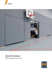
2 - Hormann
2 - Hormann
2 - Hormann

You also want an ePaper? Increase the reach of your titles
YUMPU automatically turns print PDFs into web optimized ePapers that Google loves.
CONTENTS PAGE<br />
A Supplied Items 2<br />
B Required Tools for Installation 2<br />
1 IMPORTANT SAFETY NOTES 7<br />
1.1 Important safety instructions 7<br />
1.1.1 Warranty 7<br />
1.1.2 Checking the gate/gate system 7<br />
1.2 Important instructions for safe installation 7<br />
1.2.1 Prior to installation 7<br />
1.2.2 When carrying out the installation work 7<br />
1.2.3 After installation 8<br />
1.3 Warnings 8<br />
1.4 Maintenance advice 8<br />
1.5 Information on the illustrated section 8<br />
Illustrations 24-39<br />
2 DEFINITIONS 52<br />
3 PREPARATION FOR INSTALLATION 52<br />
3.1 Installing the hinged gate operator 53<br />
3.1.1 Installation fundamentals for a long operator<br />
service life 53<br />
3.1.2 Establishing the fitting dimensions 53<br />
3.1.3 Preferred range 54<br />
3.1.4 Fastening the operator 54<br />
3.2 Installing the operator control 54<br />
3.3 Electrical connection 54<br />
3.4 Connecting standard components 54<br />
3.4.1 Connecting the operator for a single-leaf<br />
gate system 54<br />
3.4.2 Connecting the operator for a double-leaf<br />
gate system without a threshold 54<br />
3.4.3 Connecting the operator for a double-leaf<br />
gate system with a threshold 54<br />
3.4.4 Determining end-of-travel position detection 54<br />
3.5 Connecting additional components/accessories 54<br />
3.5.1 Connecting an external radio receiver 54<br />
3.5.2 Connecting an external button for the impulse<br />
control 55<br />
3.5.3 Connecting a warning light 55<br />
3.5.4 Connecting safety devices 55<br />
3.5.5 Connecting an electro lock 55<br />
4 INITIAL OPERATION OF THE OPERATOR 55<br />
4.1 General 55<br />
4.2 Overview of set-up mode 55<br />
4.3 Preparation 55<br />
4.4 Learning the gate's end-of-travel positions 56<br />
4.4.1 Detecting the CLOSE end-of-travel position via<br />
the integrated limit switch 56<br />
4.4.2 Detecting the end-of-travel position via mechanical<br />
limit stops 56<br />
4.4.3 Completion of set-up mode 57<br />
4.5 Learning the forces 57<br />
4.5.1 Changing the learned forces 57<br />
4.5.2 Creep speed 57<br />
6<br />
ENGLISH<br />
4.6 Sizes of the leaf offset 57<br />
4.7 Reversing limit 57<br />
4.8 Overview and settings of the DIL switches 58<br />
4.8.1 DIL switch 1: Single or double-leaf operation 58<br />
4.8.2 DIL switch 2: With/without leaf offset 58<br />
4.8.3 DIL switch 3: Leaf selection/size of leaf offset 58<br />
4.8.4 DIL switch 4: Set-up mode 58<br />
4.8.5 DIL switch 5: SE safety device 58<br />
4.8.6 DIL switch 6: Function of the safety device<br />
when opening 58<br />
4.8.7 DIL switch 7: Function of the safety device<br />
when closing 58<br />
4.8.8 DIL switch 8: Reversing to OPEN direction 58<br />
4.8.9 DIL switch 9 / DIL switch 10 58<br />
4.8.10 DIL switch 11: Safety photocell as a through-traffic<br />
photocell 58<br />
4.8.11 DIL switch 12: reversing limit/travel speed 59<br />
5 RADIO REMOTE CONTROL 59<br />
5.1 Hand transmitter description 59<br />
5.2 Integral radio module 59<br />
5.3 Programming the hand transmitter buttons for<br />
the integral radio module 59<br />
5.4 Deleting the data of the internal radio module 59<br />
5.5 Connecting an external radio receiver 59<br />
6 FACTORY RESET 59<br />
7 OPERATING THE HINGED GATE OPERATOR 59<br />
7.1 Reversing with force limit 60<br />
7.2 Reversing while opening 60<br />
7.3 Reversing while closing 60<br />
7.4 Behaviour during a power failure 60<br />
7.5 Behaviour following a power failure 60<br />
8 MAINTENANCE 60<br />
8.1 Operation, error and warning messages 60<br />
8.1.1 LED GN 60<br />
8.1.2 LED RD 60<br />
8.2 Error acknowledgement 61<br />
9 DISMANTLING 61<br />
10 OPTIONAL ACCESSORIES (NOT INCLUDED IN<br />
THE SCOPE OF SUPPLY) 61<br />
11 TERMS AND CONDITIONS OF THE WARRANTY 61<br />
12 TECHNICAL DATA 61<br />
13 OVERVIEW OF DIL SWITCH FUNCTIONS 63<br />
08.2007 TR10A028-A RE