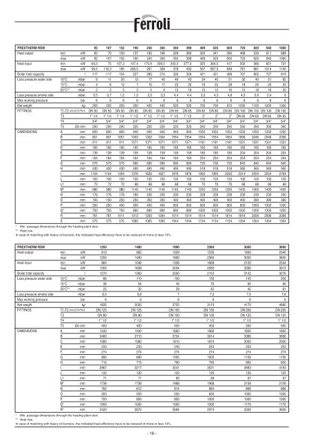
<strong>PREXTHERM</strong> <strong>RSW</strong> 92 107 152 190 240 300 350 399 469 525 600 720 820 940 1060Heat output min kW 60 70 100 137 160 196 228 260 305 341 390 468 533 611 689max kW 92 107 152 190 240 300 350 399 469 525 600 720 820 940 1060Heat input min kW 64,3 75 107,3 147,4 170,9 209,5 242,5 277,5 325 364,5 417 502 566 651 731max kW 99,5 116,3 165 206,5 261 326 378 432 507 567,5 648 781 881 1014 1140Boiler total capacity l 117 117 154 227 283 274 326 326 421 421 498 707 802 727 819Loss pressure water side 10°C mbar 8 11 20 12 17 40 48 43 34 40 51 32 40 51 6515°C mbar 4 6 12 7 10 17 23 32 18 22 28 18 25 25 3320°C** mbar 2 2 5 3 4 9 13 16 10 12 16 10 18 16 20Loss pressure smoke side mbar 0,5 0,7 1,2 1,2 2,3 3,3 4,4 4,4 3,3 4,3 4,8 4,5 5,6 5,4 6Max working pressure bar 6 6 6 6 6 6 6 6 6 6 6 6 6 6 6Net weight kg 205 205 250 350 425 455 520 520 700 700 810 1030 1105 1205 1330FITTINGS T1-T2 UNI 2278 PN16 DN 50 DN 50 DN 50 DN 65 DN 65 DN 65 DN 65 DN 65 DN 80 DN 80 DN 80 DN 100 DN 100 DN 100 DN 100T3 1” 1/4 1” 1/4 1” 1/4 1” 1/2 1” 1/2 1” 1/2 1” 1/2 1” 1/2 2” 2” 2” DN 65 DN 65 DN 65 DN 65T4 3/4” 3/4” 3/4” 3/4” 3/4” 3/4” 3/4” 3/4” 3/4” 3/4” 3/4” 3/4” 3/4” 3/4” 3/4”T5 Øe mm 200 200 200 220 220 220 220 220 250 250 250 350 350 350 350DIMENSIONS A mm 800 800 800 940 940 940 940 940 1050 1050 1050 1250 1250 1250 1250B mm 801 801 1051 1053 1303 1304 1554 1554 1554 1554 1854 1856 2046 2046 2306C mm 911 911 911 1071 1071 1071 1071 1071 1181 1181 1181 1331 1331 1331 1331D mm 165 165 165 165 165 165 165 165 165 165 165 165 165 165 165E mm 139 139 139 159 159 159 159 159 185 185 185 204 204 204 204F mm 164 164 164 164 164 164 164 164 254 254 254 254 254 254 254G mm 575 575 575 690 690 690 690 690 730 730 730 840 840 840 840H mm 430 430 430 495 495 495 495 495 518 518 518 565 565 565 565I mm 1104 1104 1354 1376 1626 1627 1876 1876 1993 1993 2293 2314 2504 2504 2764L mm 100 100 100 100 100 100 100 100 100 100 100 100 100 100 100L1 mm 72 72 72 68 68 68 68 68 70 70 70 68 68 68 68M* mm 980 980 980 1140 1140 1140 1140 1140 1250 1250 1250 1400 1400 1400 1400N mm 176 176 176 180 230 230 230 230 228 228 228 230 230 230 230O mm 150 150 250 250 350 350 400 400 400 400 400 400 390 390 390P mm 250 250 400 350 450 450 600 600 600 600 800 800 1000 1000 1000Q* mm 750 750 750 890 890 890 890 890 1000 1000 1000 1200 1200 1200 1200R mm 761 761 1011 1013 1263 1264 1514 1514 1514 1514 1814 1816 2006 2006 2266S mm 575 575 575 1065 1065 1065 1044 1044 1154 1154 1154 1354 1354 1354 1354* Min. passage dimensions through the heating plant door.** Heat rise.In case of matching with heavy oil burners, the indicated heat efficiency have to be reduced of more or less 10%.<strong>PREXTHERM</strong> <strong>RSW</strong> 1250 1480 1890 2360 3000 3600Heat output min kW 813 962 1229 1535 1950 2340max kW 1250 1480 1890 2360 3000 3600Heat input min kW 884 1046 1336 1668 2120 2544max kW 1359 1608 2054 2565 3260 3913Boiler total capacity l 1270 1363 2000 2153 3142 3276Loss pressure water side 10°C mbar 86 110 100 150 145 20015°C mbar 36 54 45 70 65 9020°C** mbar 25 32 29 42 45 61Loss pressure smoke side mbar 6,5 6,8 7 7,2 7,5 7,8Max working pressure bar 6 6 6 6 6 6Net weight kg 1835 2035 2755 3110 4170 4680FITTINGS T1-T2 UNI 2278 PN16 DN 125 DN 125 DN 150 DN 150 DN 200 DN 200T3 DN 80 DN 80 DN 100 DN 100 DN 125 DN 125T4 1” 1/2 1” 1/2 1” 1/2 1” 1/2 1” 1/2 1” 1/2T5 Øe mm 400 400 450 450 500 500DIMENSIONS A mm 1430 1430 1660 1660 1850 1850B mm 2460 2710 2724 3014 3366 3666C mm 1580 1580 1810 1810 2000 2000E mm 233 233 243 243 253 253F mm 274 274 274 274 274 274G mm 890 890 1005 1005 1100 1100H mm 715 715 790 790 850 850I mm 2967 3217 3241 3531 3893 4193L mm 120 120 120 120 120 120L1 mm 71 71 69 69 67 67M* mm 1738 1738 1968 1968 2158 2158N mm 762 812 814 864 866 866O mm 500 550 550 650 1000 1000P mm 700 850 850 1000 1000 1000Q* mm 1000 1000 1000 1000 1170 1170R* mm 2420 2670 2684 2974 3326 3626* Min. passage dimensions through the heating plant door.** Heat rise.In case of matching with heavy oil burners, the indicated heat efficiency have to be reduced of more or less 10%.- 16 -
5. INSTALLATION5.1 PackagingThe <strong>PREXTHERM</strong> <strong>RSW</strong> boilers are suppliedcomplete with: door, smokebox and insulationalready installed, while the panels are containedin a separate cardboard box.The instrument panel and the layer of ceramicfibre for the burner draught tube are placed insidethe combustion chamber.Model 1250-3600 <strong>RSW</strong> boilers are suppliedcomplete with the insulation and casing.The instrument panel is supplied in a cardboardbox and positioned inside the combustionchamber.5.2 HandlingThe <strong>PREXTHERM</strong> <strong>RSW</strong> boilers are fitted witheyebolts for lifting. Make sure the hoisting equipmentused is suitable for the weight being lifted.Before positioning the boiler, remove the woodenbase support by unscrewing the fasteningscrews (Fig. 5).5.3 Boiler room (Fig. 6)The <strong>PREXTHERM</strong> <strong>RSW</strong> boilers should beinstalled in rooms exclusively used for this purpose,in accordance with the technical standardsand legislation in force and featuring adequatelysized ventilation openings.The ventilation openings must be permanent,directly communicating with the outside andlocated in both a high and low position, in compliancewith the standards in force.The location of the ventilation openings, the fuelsupply, power and lighting circuits must complywith the legislation in force in relation to the typeof fuel used. To assist the cleaning of the flue gascircuit, free space must be left at the front of theboiler no less than the length of the boiler bodyand, in any case, never less than 1300 mm,checking that with the door open at 90° the distancebetween the door and the adjacent wall (X), isat least equal to the length of the burner. The boilersupport surface must be perfectly horizontal. Aflat cement base should be used that is able tosupport the overall weight of the boiler plus thewater content. For the dimensions of the base,see the distances R x Q (table of dimensions). Ifthe burner is supplied with gas fuel whose specificweight is higher than air, the electrical parts mustbe located more than 500 mm from the floor. Theappliance cannot be installed outdoors as it is notdesigned to operate outside and does not featureautomatic frost protection systems.INSTALLATION IN OLD SYSTEMSOR SYSTEMS TO BE UPGRADEDWhen the boiler is installed in old systems orsystems to be upgraded, check that:- The flue stack is suitable for the temperatureof the products of combustion, calculated andmanufactured according to the standards inforce, airtight, insulated and not blocked orchoked.- The electrical system has been installed incompliance with the relevant standards byqualified personnel.- The fuel supply line and any tanks are madeaccording to the relevant standards.- The expansion vessel/vessels can completelyabsorb the expansion of the fluid contained inthe system.- The flow-rate, discharge head and the directionof the flow of the circulating pumps aresuitable.- The system is washed, cleaned of slime, fouling,vented and watertight.-A treatment system is available for specialsupply/top-up water requirements (see thereference values).5.4 Discharge of the products of combustion(Fig. 7)The flue and the flue fitting must be made incompliance with the standards and the legislationin force, using rigid pipes that are resistantto high temperatures, condensate and mechanicalstress, and are airtight.The flue must ensure the minimum negativepressure specified by the standards in force,considering “zero” pressure at the fitting to theflue. Unsuitable or incorrectly sized flues mayincrease the noise produced due to combustion,generate problems involving condensation andnegatively affect the combustion parameters.Non-insulated flues are a source of potentialdanger. The joint seals should be made usingmaterials that can resist temperatures of at least250°C. Suitable points for measuring the fluegas temperature and analysing the products ofcombustion must be prepared in the connectionbetween the boiler and the flue. As regards thecross-section and the height of the chimney,refer to the national and local standards in force.5.5 Water connections5.5.1 Supply waterThe chemical characteristics of the supply andtop-up water are fundamental for the correct operationand the safety of the boiler. The watershould be treated using suitable systems.The values shown in the table below can be usedas references.TOTAL HARDNESS ppm 10ALKALINITY mg/l CaCO 3 750PH 8÷9SILICA ppm 100CHLORIDES ppm 3500The water used in the central heating systemmust be treated in the following cases:- Very large systems- Very hard water- Frequent introduction of water to top up thesystem.If, in these cases, the system needs to be partiallyor completely emptied, it must be refilledwith treated water. To control the volume ofwater automatically refilled, an hour countershould be installed. The most common phenomenathat occur in heating systems are:- Lime scale depositsLime scale tends to concentrate at the pointswhere the temperature of the wall is higher.Due to their low heat conductivity, lime scaledeposits cause a reduction in heat exchangeto the extent that even when just a few millimetresthick, the heat exchange between theflue gas and the water is limited, bringing anincrease in the temperature of the parts exposedto the flame and consequently breakages(cracks) on the tube plate.- Corrosion on the water sideCorrosion of the metal surfaces on the waterside of the boiler is due to the dissolution ofiron into its ions. The presence of dissolvedgases, in particular oxygen and carbonicdioxide, play and important part in this process.Softened and/or demineralised waterprovides protection against lime scale andother deposits, however does not protectagainst corrosion. The water therefore mustbe treated with corrosion inhibitors.5.5.2 Central heating outlet/return pipesThe dimensions of the outlet and return pipesare shown for each model of the boiler, in thetable of DIMENSIONS.Check that the system features a sufficient numberof vent openings. The boiler fittings must notbe stressed by the weight of the connectionpipes to the system, and consequently specialsupports must be installed.5.5.3 System fill/drain pipesTo fill and drain the boiler, a cock can be connectedto fitting T4 at the rear (see the drawingof the DIMENSIONS).5.5.4 Expansion vessel and safety valve pipesThe <strong>PREXTHERM</strong> <strong>RSW</strong> boilers are suitable foroperation with forced water circulation, both withopen and closed expansion vessels.An expansion vessel is always required, to allowfor the increase in water volume due to heating.In the first case, the height of the hydrostaticcolumn must be at least 3 metres above the boilercasing and must have a sufficient capacity tocontain, between the surface of the water in thevessel and the overflow pipe, the increase involume of all the water in the system.High and narrow vessels are better, as theyensure minimum contact between the water surfaceand the air, thus reducing evaporation.In the second case, the capacity of the closedexpansion vessel must be calculated considering:- the total volume of water contained in the system- the maximum operating pressure of the system- the maximum operating pressure of theexpansion vessel- the initial pre-charge pressure of the expansionvessel- the maximum operating temperature of theboiler (the maximum temperature of the thermostatfitted on the panel is 90°C; whenperforming this calculation, use the value100°C).The expansion pipes connect the expansionvessel to the system. This pipes that run fromfitting T3 (see the table of Dimensions), mustnot be fitted with on-off valves. On fitting T3, oron the outlet pipe, within 0.5 metres from thefirst flange, install a safety valve sized for thecapacity of the boiler and in compliance with thelocal standards in force. No type of shut-off devicemay be installed between the boiler and theexpansion vessel, and between the boiler andthe safety valves, while the valves should calibratedfor activation at values no higher than themaximum admissible operating pressure.GB- 17 -
- Page 1: PREXTHERM RSW
- Page 5 and 6: 1. PRESENTAZIONEGentile Cliente,La
- Page 7 and 8: 5. INSTALLAZIONE5.1 ImballoLe calda
- Page 9 and 10: 6. PANNELLO STRUMENTI STANDARD6.1 P
- Page 11 and 12: Legenda simboli/componenti schema e
- Page 13 and 14: ANOMALIAIL GENERATORE SI SPORCA FAC
- Page 15: 1. PRESENTATIONDear Customer,Thank
- Page 19 and 20: 6. STANDARD INSTRUMENT PANEL6.1 Pan
- Page 21 and 22: Key to the symbols/components on th
- Page 23 and 24: FAULTTHE BOILER DIRTIES QUITE EASIL
- Page 25 and 26: 1. PRESENTATIONCher client,Nous vou
- Page 27 and 28: 5. INSTALLATION5.1 EmballageLes cha
- Page 29: 6. PANNEAU INSTRUMENTS STANDARD6.1
- Page 32 and 33: n'y a pas de fuite sur le réseau d
- Page 34 and 35: ÍNDICE1. Presentación . . . . . .
- Page 36 and 37: PREXTHERM RSW 92 107 152 190 240 30
- Page 38 and 39: de seguridad, y se recomienda que d
- Page 40 and 41: 6.4 Esquema eléctrico para quemado
- Page 42 and 43: dentro del campo de potencia declar
- Page 45 and 46: 1. PRÆSENTATIONKære Kunde!Vi takk
- Page 47 and 48: 5. INSTALLATION5.1 EmballageVed lev
- Page 49 and 50: 6. STANDARDINSTRUMENTPANEL6.1 Panel
- Page 51 and 52: Oversigt over symboler/komponenter
- Page 53 and 54: FORSTYRRELSEKEDLEN BLIVER LET SNAVS
- Page 55 and 56: 1. VORWORTVerehrter Kunde,Wir danke
- Page 57 and 58: 5. INSTALLATION5.1 VerpackungDer Li
- Page 59 and 60: vorher mit einem geeigneten Lösemi
- Page 61 and 62: Zeichenerklärung Symbole/Komponent
- Page 63 and 64: BETRIEBSSTÖRUNGDER WÄRMEERZEUGER
- Page 65 and 66: 1. PRESENTATIEGeachte klant,Dank u
- Page 67 and 68:
5. INSTALLATIE5.1 VerpakkingDe PREX
- Page 69 and 70:
geschikt oplosmiddel, en het label
- Page 71 and 72:
Legenda symbolen/componenten op ele
- Page 73 and 74:
STORINGDE KETEL WORDT GEMAKKELIJK V
- Page 75 and 76:
1. APRESENTAÇÃOEstimado Cliente,O
- Page 77 and 78:
5. INSTALAÇÃO5.1 EmbalagemAs cald
- Page 79 and 80:
6. PAINEL DE INSTRUMENTOS STANDARD6
- Page 81 and 82:
Legenda de símbolos/componentes do
- Page 83 and 84:
ANOMALIAO GERADOR SUJA-SE FACILMENT
- Page 85 and 86:
1. PRESENTATIONBäste kund,Vi tacka
- Page 87 and 88:
5. INSTALLATION5.1 FörpackningPann
- Page 89 and 90:
6. STANDARD INSTRUMENTPANEL6.1 Pane
- Page 91 and 92:
Förteckning över symboler/kompone
- Page 93 and 94:
FELPANNAN SMUTSAS LÄTT NEDORSAK: B
- Page 95 and 96:
1. ESITTELYArvoisa asiakas,Kiitämm
- Page 97 and 98:
5. ASENNUS5.1 PakkausPREXTHERM RSW
- Page 99 and 100:
6. PERUSMITTARITAULU6.1 Mittaritaul
- Page 101 and 102:
Symbolien selitykset/sähkökaavion
- Page 103 and 104:
TOIMINTAHÄIRIÖLÄMMITYSKATTILA LI
- Page 105 and 106:
1Fig. 4 Fig. 510006001000600XFig. 6
- Page 107 and 108:
6Per la messa a terra del corpo cal
- Page 112:
FERROLI S.p.A.via Ritonda 78/A ¬ 3