approved output range of the boiler. After havingopened the fuel on-off cocks and checked thatthere are no leaks in the supply line, place allthe switches on the ON position. The burner willthus be ready for first ignition and for the adjustmentsto be made by the authorised technician.On first ignition, check that the door, the burnerflange and the connections to the chimney aretight and that there is a slight negative pressureat the base of the flue. The fuel rate must correspondto the boiler's rated data and under nocircumstances must exceed the maximum outputvalue declared. The temperature of the fluegas must never fall below 160°C.8.3 Shutting down the boiler- Set the temperature controller to the minimum.- Disconnect power from the burner and closethe fuel supply.- Let the pumps operate until they are stoppedby the temperature controller.- Disconnect power from the electrical panel.9. MAINTENANCE9.1 General instructionsPeriodical maintenance is essential for thesafety, efficiency and long life of the appliance.All the operations must be carried out by qualifiedpersonnel. All cleaning and maintenance operationsmust be performed after having closed thefuel supply and disconnected the power supply.For the correct operation and maximum efficiencyof the boiler, the combustion chamber, fire tubesand smokebox must be cleaned regularly.9.2 Routine maintenanceThe interval between cleaning operations mustbe established by the user based on the experienceacquired on each individual system, consequentlythe maintenance intervals cannot beestablished in advance.In any case, the following minimum intervals arerecommended, according to the fuel used:- Gas: once a year- Oil: twice a year- Fuel oil: every 300 hours of operationIn any case, any local maintenance standards inforce should be observed. During the routinemaintenance operations, after having removedthe turbulators, brush the tube bundle and thefurnace. Remove the deposits accumulated inthe smokebox by opening the inspection doors.For more intense cleaning, remove the rearsmokebox and, if deteriorated, replace the fluegas seal. Check that the condensate drain is notblocked. Ensure that the control and measurementdevices serving the boiler are working correctly.Measure the amount of top-up wateradded, and after having analysed the water, adddescaler. The calcium and magnesium salts dissolvedin the water will, after repeated refills,cause deposits in the boiler and the overheatingof the metal plate, with possible damage that isnot attributable to materials or workmanship,and consequently not covered by the warranty.After having completed the maintenance andcleaning operations and started the boiler again,check the tightness of the door and the smokebox,and in the event of gas leaks, replace thecorresponding gaskets.The operations carried out must be enteredin the system logbook.9.3 Special maintenanceSpecial maintenance to be performed at the endof the season or for extended shutdowns.All the operations described in the previouschapter must be completed, plus the followingadditional operations:- Check the condition of the turbulators for wear.- After cleaning the flue gas circuit, wipe with arag dipped in a diluted solution of caustic soda.After having left to dry, wipe all the surfaceswith a rag dipped in oil.- Hygroscopic substances (quicklime, silica gelin small containers) should be placed insidethe furnace, which must then be closed hermeticallyso that air cannot enter.- Do not empty the system and the boiler.- Protect the screws, nuts and pins on the doorwith graphite grease.The operations carried out must be enteredin the system logbook.9.4 Cleaning the boiler (Fig. 19)To clean the boiler, proceed as follows:- Open the front door (1) and remove the turbulators(2).- Clean the inside surfaces of the combustionchamber and the flue gas path using a brush(3) or other suitable implements.- Remove the deposits accumulated in thesmokebox by opening the inspection door (4).For more intense cleaning, remove the smokeboxcover (5) and replace the gasket beforereassembling.- Periodically check that the condensate drain(6) is not blocked.9.5 Checking the operation of the boilerBefore staring and running the functional testson the boiler, make sure that:- The turbulators are positioned against theexchanger tubes.- The cocks in the water circuit and on the fuellines are open.- Fuel is available.- The expansion vessel is suitably filled.- The pressure of the water circuit, when cold, ismore than 1 bar and less than the maximumlimit allowed for the boiler.- The water circuits have been vented.- The electrical connections to the mains powerand the components (burner, pump, controlpanel, thermostats etc.) have been completed.- The phase-neutral connection must be observed,and the earth must be connected.After having performed the operations describedabove, the following operations are necessary tostart the boiler:- If the system is fitted with a temperature controlleror timer-thermostat, check that theseare “on”.- Set the room timer-thermostat or the temperaturecontroller to the desired temperature.- Move the main system switch to “on”- Set the boiler thermostat located on thecontrol panel- Move the main switch on the control panel to“on” and check that the green indicator lightcomes on.The boiler will run the ignition phase and willremain on until the set temperature has beenreached. If problems occur during ignition oroperation, the boiler will “LOCKOUT”, as signalledby the red light on the burner and the redindicator on the control panel. After a“LOCKOUT”, wait around 30 seconds beforerestoring the ignition conditions. To restore theignition conditions, press the burner“button/light” and wait for the flame to ignite. Ifthis operation fails, it can be repeated a maximum2-3 times, then check:- The information provided in the burner instructionbooklet.- The chapter on “CHECKING THE OPERA-TION OF THE BOILER”.- The electrical connections described on thediagram supplied with the control panel.When the boiler has started, check that it stopsand starts again:- Adjust the setting of the boiler thermostat.- Move the main switch on the control panel.- Set the room thermostat, the timer or the temperaturecontroller.- Check that the pumps are not blocked androtate in the correct direction.- Check the total shutdown of the boiler usingthe main system switch.If all the conditions are correct, restart theappliance, check the combustion (flue gasanalysis), the fuel rate and the tightness of thegaskets on the door and the smokebox.9.6 Checking the operation of the burner- Refer to the burner instruction manual.- Follow all the local legislation in force onburner maintenance.9.7 TroubleshootingThe following is a list with information on themain faults or problems that may occur duringthe operation of the boiler, showing the possiblecauses and corresponding solutions.- 22 -
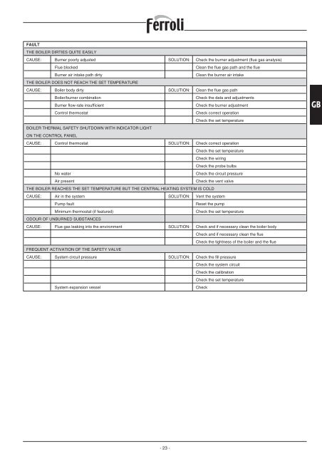
FAULTTHE BOILER DIRTIES QUITE EASILYCAUSE: Burner poorly adjusted SOLUTION: Check the burner adjustment (flue gas analysis)Flue blockedClean the flue gas path and the flueBurner air intake path dirtyClean the burner air intakeTHE BOILER DOES NOT REACH THE SET TEMPERATURECAUSE: Boiler body dirty SOLUTION: Clean the flue gas pathBoiler/burner combinationCheck the data and adjustmentsBurner flow-rate insufficientCheck the burner adjustmentControl thermostatCheck correct operationCheck the set temperatureBOILER THERMAL SAFETY SHUTDOWN WITH INDICATOR LIGHTON THE CONTROL PANELCAUSE: Control thermostat SOLUTION: Check correct operationCheck the set temperatureCheck the wiringCheck the probe bulbsNo waterCheck the circuit pressureAir presentCheck the vent valveTHE BOILER REACHES THE SET TEMPERATURE BUT THE CENTRAL HEATING SYSTEM IS COLDCAUSE: Air in the system SOLUTION: Vent the systemPump faultReset the pumpMinimum thermostat (if featured)Check the set temperatureODOUR OF UNBURNED SUBSTANCESCAUSE: Flue gas leaking into the environment SOLUTION: Check and if necessary clean the boiler bodyCheck and if necessary clean the flueCheck the tightness of the boiler and the flueFREQUENT ACTIVATION OF THE SAFETY VALVECAUSE: System circuit pressure SOLUTION: Check the fill pressureCheck the system circuitCheck the calibrationCheck the set temperatureSystem expansion vesselCheckGB- 23 -
- Page 1: PREXTHERM RSW
- Page 5 and 6: 1. PRESENTAZIONEGentile Cliente,La
- Page 7 and 8: 5. INSTALLAZIONE5.1 ImballoLe calda
- Page 9 and 10: 6. PANNELLO STRUMENTI STANDARD6.1 P
- Page 11 and 12: Legenda simboli/componenti schema e
- Page 13 and 14: ANOMALIAIL GENERATORE SI SPORCA FAC
- Page 15 and 16: 1. PRESENTATIONDear Customer,Thank
- Page 17 and 18: 5. INSTALLATION5.1 PackagingThe PRE
- Page 19 and 20: 6. STANDARD INSTRUMENT PANEL6.1 Pan
- Page 21: Key to the symbols/components on th
- Page 25 and 26: 1. PRESENTATIONCher client,Nous vou
- Page 27 and 28: 5. INSTALLATION5.1 EmballageLes cha
- Page 29: 6. PANNEAU INSTRUMENTS STANDARD6.1
- Page 32 and 33: n'y a pas de fuite sur le réseau d
- Page 34 and 35: ÍNDICE1. Presentación . . . . . .
- Page 36 and 37: PREXTHERM RSW 92 107 152 190 240 30
- Page 38 and 39: de seguridad, y se recomienda que d
- Page 40 and 41: 6.4 Esquema eléctrico para quemado
- Page 42 and 43: dentro del campo de potencia declar
- Page 45 and 46: 1. PRÆSENTATIONKære Kunde!Vi takk
- Page 47 and 48: 5. INSTALLATION5.1 EmballageVed lev
- Page 49 and 50: 6. STANDARDINSTRUMENTPANEL6.1 Panel
- Page 51 and 52: Oversigt over symboler/komponenter
- Page 53 and 54: FORSTYRRELSEKEDLEN BLIVER LET SNAVS
- Page 55 and 56: 1. VORWORTVerehrter Kunde,Wir danke
- Page 57 and 58: 5. INSTALLATION5.1 VerpackungDer Li
- Page 59 and 60: vorher mit einem geeigneten Lösemi
- Page 61 and 62: Zeichenerklärung Symbole/Komponent
- Page 63 and 64: BETRIEBSSTÖRUNGDER WÄRMEERZEUGER
- Page 65 and 66: 1. PRESENTATIEGeachte klant,Dank u
- Page 67 and 68: 5. INSTALLATIE5.1 VerpakkingDe PREX
- Page 69 and 70: geschikt oplosmiddel, en het label
- Page 71 and 72: Legenda symbolen/componenten op ele
- Page 73 and 74:
STORINGDE KETEL WORDT GEMAKKELIJK V
- Page 75 and 76:
1. APRESENTAÇÃOEstimado Cliente,O
- Page 77 and 78:
5. INSTALAÇÃO5.1 EmbalagemAs cald
- Page 79 and 80:
6. PAINEL DE INSTRUMENTOS STANDARD6
- Page 81 and 82:
Legenda de símbolos/componentes do
- Page 83 and 84:
ANOMALIAO GERADOR SUJA-SE FACILMENT
- Page 85 and 86:
1. PRESENTATIONBäste kund,Vi tacka
- Page 87 and 88:
5. INSTALLATION5.1 FörpackningPann
- Page 89 and 90:
6. STANDARD INSTRUMENTPANEL6.1 Pane
- Page 91 and 92:
Förteckning över symboler/kompone
- Page 93 and 94:
FELPANNAN SMUTSAS LÄTT NEDORSAK: B
- Page 95 and 96:
1. ESITTELYArvoisa asiakas,Kiitämm
- Page 97 and 98:
5. ASENNUS5.1 PakkausPREXTHERM RSW
- Page 99 and 100:
6. PERUSMITTARITAULU6.1 Mittaritaul
- Page 101 and 102:
Symbolien selitykset/sähkökaavion
- Page 103 and 104:
TOIMINTAHÄIRIÖLÄMMITYSKATTILA LI
- Page 105 and 106:
1Fig. 4 Fig. 510006001000600XFig. 6
- Page 107 and 108:
6Per la messa a terra del corpo cal
- Page 112:
FERROLI S.p.A.via Ritonda 78/A ¬ 3