REMS Picus S1 REMS Picus S3 REMS Picus S2 / 3,5 REMS Picus ...
REMS Picus S1 REMS Picus S3 REMS Picus S2 / 3,5 REMS Picus ...
REMS Picus S1 REMS Picus S3 REMS Picus S2 / 3,5 REMS Picus ...

Create successful ePaper yourself
Turn your PDF publications into a flip-book with our unique Google optimized e-Paper software.
eng fra<br />
Remedy: Switch off drive unit. Use an SW 41 wrench to turn the diamond core<br />
drilling crown back and forth in order to free it. Care fully continue<br />
the drilling operation. Use a dust extrac tion system, or wet-boring.<br />
5.2. Fault: Diamond core drilling crown jams or cuts only with difficulty.<br />
Cause: Loose material or metal debris have jammed up the mechanism.<br />
Remedy: Break up the drilling core and remove loose items.<br />
Cause: Casing pipe is out-of-true or damaged.<br />
Remedy: Use a new diamond core drilling crown.<br />
5.3. Fault: Diamond core drilling crown cuts with difficulty.<br />
Cause: Incorrect turning speed (<strong>REMS</strong> <strong>Picus</strong> <strong>S3</strong>, <strong>REMS</strong> <strong>Picus</strong> <strong>S2</strong>/3,5, <strong>REMS</strong><br />
<strong>Picus</strong> SR).<br />
Polished diamond-tipped segments.<br />
Remedy: Increase feed pressure.<br />
Sharpen the diamond-tipped segments. This is done by drilling into<br />
sandstone, asphalt or a sharpening stone (available as an accessory)<br />
to a depth of 10 mm to 15 mm.<br />
Cause: Worn diamond-tipped segments.<br />
Remedy: Use a new diamond core drilling crown.<br />
5.4. Fault: Diamond core drilling crown does not tap a hole, or slips to one<br />
side.<br />
Cause: Excess pressure on the diamond core drilling crown during tapping.<br />
Remedy: Operate at a reduced feed rate.<br />
Cause: The drive unit is incorrectly secured to the clamping angle<br />
Remedy: Check the drill collar to ensure that it is correctly attached to the drive<br />
unit.<br />
Cause: Damaged or out-of-true diamond core drilling crown.<br />
Remedy: Use a new diamond core drilling crown.<br />
Cause: Drill upright not properly secured.<br />
Remedy: Tighten fixing screw and adjustment screws.<br />
5.5. Fault: Drilling core remains hanging in diamond core drilling crown.<br />
Cause: Compressed drilling dust in casing pipe jams parts of the drilling<br />
core.<br />
Remedy: DO NOT knock the casing pipe with metal objects of any kind (e.g.<br />
hammer, wrench). This will cause the casing pipe to become dented,<br />
which will make blocking of the drilling core even more likely on future<br />
occasions. The diamond core drilling crown may then be rendered<br />
unusable.<br />
Unscrew the diamond core drilling crown from the drive unit, eject<br />
the drilling core with a rod, taking care not to damage the connection<br />
thread.<br />
5.6. Fault: Diamond core drilling crown is detached from drive spindle with<br />
difficulty.<br />
Cause: Dirt, corrosion.<br />
Remedy: Clean and slightly oil the thread of the drive spindle and the diamond<br />
core drilling crown.<br />
5.7. Fault: Drive unit will not run.<br />
Cause: Fault-current safety switch PRCD (19) not actuated.<br />
Remedy: Check PRCD (see 3.).<br />
Contact an electrician.<br />
6. Disposal<br />
The units may not be thrown into the domestic waste at the end of use. They<br />
must be disposed of properly by law.<br />
7. Manufacturer’s Warranty<br />
The warranty period shall be 12 months from delivery of the new product to the<br />
first user. The date of delivery shall be documented by the submission of the<br />
original purchase documents, which must include the date of purchase and the<br />
designation of the product. All functional defects occurring within the warranty<br />
period, which are clearly the consequence of defects in production or materials,<br />
will be remedied free of charge. The remedy of defects shall not extend or<br />
renew the warranty period for the product. Damage attributable to natural wear<br />
and tear, incorrect treatment or misuse, failure to observe the operational<br />
instructions, unsuitable operating materials, excessive demand, use for unauthorized<br />
purposes, interventions by the customer or a third party or other<br />
reasons, for which <strong>REMS</strong> is not responsible, shall be excluded from the warranty<br />
Services under the warranty may only be provided by customer service stations<br />
authorized for this purpose by <strong>REMS</strong>. Complaints will only be accepted if the<br />
product is returned to a customer service station authorized by <strong>REMS</strong> without<br />
prior interference in an unassembled condition. Replaced products and parts<br />
shall become the property of <strong>REMS</strong>.<br />
The user shall be responsible for the cost of shipping and returning the product.<br />
The legal rights of the user, in particular the right to make claims against the<br />
seller under the warranty terms, shall not be affected. This manufacturer’s<br />
warranty only applies for new products which are purchased in the European<br />
Union, in Norway or in Switzerland.<br />
This warranty is subject to German law with the exclusion of the United Nations<br />
Convention on Contracts for the International Sales of Goods (CISG).<br />
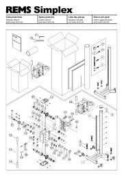
8. Spare parts lists<br />
For spare parts lists, see www.rems.de → Downloads → Parts lists.<br />
Traduction de la notice d’utilisation originale<br />
Fig. 1 <strong>REMS</strong> <strong>Picus</strong> <strong>S1</strong><br />
Fig. 2 <strong>REMS</strong> <strong>Picus</strong> <strong>S3</strong><br />
Fig. 3 <strong>REMS</strong> <strong>Picus</strong> <strong>S2</strong>/3,5<br />
Fig. 4 Carottage à sec à guidage manuel avec guide d’amorce<br />
Fig. 5 Fixation de la colonne de carottage dans le béton avec des chevilles<br />
d’ancrage<br />
Fig. 6 Fixation de la colonne de carottage dans un mur maçonné avec cheville<br />
écarteurs (ancre à cuvette)<br />
Fig. 7 Plaque signalétique <strong>REMS</strong> <strong>Picus</strong> <strong>S3</strong><br />
Fig. 8 Plaque signalétique <strong>REMS</strong> <strong>Picus</strong> <strong>S2</strong>/3,5<br />
Fig. 9 1) Réglage de la vitesse de rotation pour <strong>REMS</strong> <strong>Picus</strong> SR<br />
2) Béton Ø mm<br />
3) Maçonnerie Ø mm<br />
4) Vitesse de rotation n ¹/min<br />
5) Transmission à 2 rapports<br />
6) Régulateur électronique<br />
Fig. 1 – 12<br />
1 Colonne de carottage<br />
2 Chariot d’avance<br />
4 Levier d’avance<br />
5 Vis de réglage<br />
6 Socle<br />
7 Fente<br />
8 Vis cylindrique<br />
10 Pièce de serrage<br />
11 Broche d’entraînement<br />
12 Poignée d’appui (surface isolée)<br />
13 Col de serrage<br />
14 Couvercle<br />
15 Dispositif d’amenée d’eau<br />
16 Interrupteur de sécurité témoin<br />
lumineux<br />
17 Interrupteur de sécurité touche<br />
RESET<br />
18 Interrupteur de sécurité touche<br />
TEST<br />
19 Interrupteur de sécurité F1 (déclenchement<br />
par courant de défaut)<br />
20 Poignée moteur (surface isolée)<br />
21 Interrupteur<br />
22 Adaptateur<br />
23 Cheville d’ancrage<br />
24 Chasse<br />
25 Tige filetée à moletage<br />
26 Rondelle<br />
27 Ecrou de serrage rapide<br />
28 Cheville écarteurs<br />
29 Tête de serrage<br />
30 Contre-écrou<br />
31 Vis<br />
32 Vis à ailettes<br />
33 Tige filetée<br />
34 Vis à tête cylindrique<br />
37 Vis<br />
Consignes générales de sécurité<br />
38 Set entretoise<br />
39 Manette commutatrice<br />
40 Jambe de force<br />
41 Raccord tuyau<br />
42 Couvercle<br />
43 Joint<br />
44 Dispositif d’aspiration d’eau<br />
45 Rondelle caoutchouc<br />
46 Rotor d’aspiration<br />
47 Raccord pour couronnes de<br />
carottage UNC 1¼ et G ½<br />
48 Couronne de carottage diamantée<br />
49 Guide d’amorce de carottage<br />
50 Rallonge des couronnes de<br />
carottage<br />
51 Réservoir d’eau sous pression<br />
52 Vis<br />
53 Flasque de fixation<br />
54 Anneau pour dévissage facile<br />
55 Pierre à affûter<br />
56 Bloc de niveau<br />
57 Molette de réglage<br />
58 Pointeur laser de centrage<br />
59 Vis de fixation du câble de terre<br />
60 Perçage taraudé<br />
61 Étrier<br />
62 Set de serrage rapide 160<br />
63 Set de serrage rapide 500<br />
64 Gabarit de perçage <strong>REMS</strong> Titan<br />
65 Foret béton en métal dur Ø 15 mm<br />
SDS-plus<br />
66 Foret béton en métal dur Ø 20 mm<br />
SDS-plus<br />
67 Pompe à vide<br />
68 Foret pour carrelage<br />
69 Guide d’amorce avec fixation sous<br />
vide<br />
AVERTISSEMENT<br />
Toutes les directives doivent être lues. Le non-respect des instructions présentées<br />
ci-après peuvent entraîner un risque de décharge électrique, de brûlures et/ou<br />
d’autres blessures graves. Le terme utilisé ci-après « appareil électrique » se réfère<br />
aux outils électriques sur secteur (avec câble de réseau), aux outils électriques sur<br />
accu (sans câble de réseau), aux machines et aux outils électriques. N’utiliser<br />
l’appareil que pour accomplir les tâches pour lesquelles il a été spécialement conçu<br />
et conformément aux prescriptions relatives à la sécurité du travail et à la prévention<br />
des accidents.<br />
CONSERVER PRECIEUSEMENT CES INSTRUCTIONS<br />
A) Poste de travail<br />
a) Maintenir le poste de travail propre et rangé. Le désordre et un poste de travail<br />
non éclairé peut être source d’accident.<br />
b) Ne pas travailler avec l’appareil électrique dans un milieu où il existe un<br />
risque d’explosion, notamment en présence de liquides, de gaz ou de<br />
poussières inflammables. Les appareils électriques produisent des étincelles,<br />
qui peuvent mettre le feu à la poussière ou aux vapeurs.<br />
c) Tenir les enfants et des tierces personnes à l’écart pendant l’utilisation de<br />
l’appareil électrique. Il y a un risque de perte de contrôle de la machine en cas<br />
de distraction.<br />
B) Sécurité électrique<br />
a) La fiche mâle de l’appareil électrique doit être appropriée à la prise de<br />
courant. La fiche mâle ne doit en aucun cas être modifée. Ne pas utiliser<br />
d’adaptateur de fiche mâle avec un appareil électrique avec mise à la terre.<br />
Des fiches mâles non modifiées et des prises de courant appropriées réduisent<br />
le risque d’une décharge électrique. Si l’appareil est doté d’un conducteur de