

Breaker Interface Module II - Eaton Canada
Breaker Interface Module II - Eaton Canada
Breaker Interface Module II - Eaton Canada

You also want an ePaper? Increase the reach of your titles
YUMPU automatically turns print PDFs into web optimized ePapers that Google loves.
I.B. 29C893B Page 5<br />
the LEDs when lit are red, except for the Operational<br />
LED which is green. LEDs are used to indicate a number<br />
of functions, operations and/or warnings.<br />
Four LED type display windows are used to display an<br />
array of metered parameters, setpoints, messages and<br />
addresses in a number of different formats. The information<br />
is presented in the form of display screens for a<br />
variety of categories.<br />
The operator panel contains eight membrane pushbuttons.<br />
Pushbuttons accomplish their function when<br />
pressed and then released. Certain pushbuttons will,<br />
however, continue to scroll if they are pressed and not<br />
released.<br />
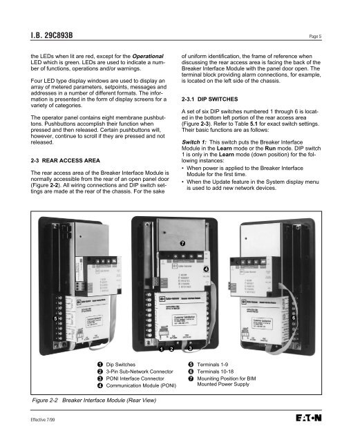
2-3 REAR ACCESS AREA<br />
The rear access area of the <strong>Breaker</strong> <strong>Interface</strong> <strong>Module</strong> is<br />
normally accessible from the rear of an open panel door<br />
(Figure 2-2). All wiring connections and DIP switch settings<br />
are made at the rear of the chassis. For the sake<br />
Effective 7/99<br />
5<br />
Figure 2-2 <strong>Breaker</strong> <strong>Interface</strong> <strong>Module</strong> (Rear View)<br />
1<br />
2<br />
3<br />
4<br />
1 2 3<br />
Dip Switches<br />
3-Pin Sub-Network Connector<br />
PONI <strong>Interface</strong> Connector<br />
Communication <strong>Module</strong> (PONI)<br />
of uniform identification, the frame of reference when<br />
discussing the rear access area is facing the back of the<br />
<strong>Breaker</strong> <strong>Interface</strong> <strong>Module</strong> with the panel door open. The<br />
terminal block providing alarm connections, for example,<br />
is located on the left side of the chassis.<br />
2-3.1 DIP SWITCHES<br />
A set of six DIP switches numbered 1 through 6 is located<br />
in the bottom left portion of the rear access area<br />
(Figure 2-3). Refer to Table 5.1 for exact switch settings.<br />
Their basic functions are as follows:<br />
Switch 1: This switch puts the <strong>Breaker</strong> <strong>Interface</strong><br />
<strong>Module</strong> in the Learn mode or the Run mode. DIP switch<br />
1 is only in the Learn mode (down position) for the following<br />
instances:<br />
• When power is applied to the <strong>Breaker</strong> <strong>Interface</strong><br />
<strong>Module</strong> for the first time.<br />
• When the Update feature in the System display menu<br />
is used to add new network devices.<br />
7<br />
5<br />
6<br />
7<br />
4<br />
Terminals 1-9<br />
Terminals 10-18<br />
Mouniting Position for BIM<br />
Mounted Power Supply<br />
6


