

Breaker Interface Module II - Eaton Canada
Breaker Interface Module II - Eaton Canada
Breaker Interface Module II - Eaton Canada

You also want an ePaper? Increase the reach of your titles
YUMPU automatically turns print PDFs into web optimized ePapers that Google loves.
I.B. 29C893B Page 7<br />
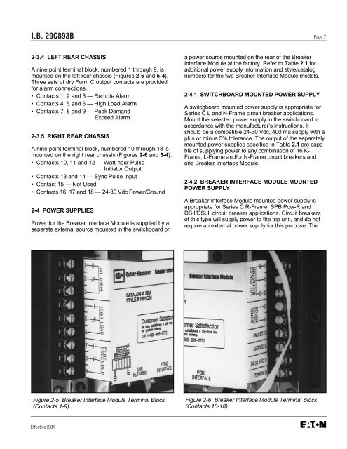
2-3.4 LEFT REAR CHASSIS<br />
A nine point terminal block, numbered 1 through 9, is<br />
mounted on the left rear chassis (Figures 2-5 and 5-4).<br />
Three sets of dry Form C output contacts are provided<br />
for alarm connections.<br />
• Contacts 1, 2 and 3 — Remote Alarm<br />
• Contacts 4, 5 and 6 — High Load Alarm<br />
• Contacts 7, 8 and 9 — Peak Demand<br />
Exceed Alarm<br />
2-3.5 RIGHT REAR CHASSIS<br />
A nine point terminal block, numbered 10 through 18 is<br />
mounted on the right rear chassis (Figures 2-6 and 5-4).<br />
• Contacts 10, 11 and 12 — Watt-hour Pulse<br />
Initiator Output<br />
• Contacts 13 and 14 — Sync Pulse Input<br />
• Contact 15 — Not Used<br />
• Contacts 16, 17 and 18 — 24-30 Vdc Power/Ground<br />
2-4 POWER SUPPLIES<br />
Power for the <strong>Breaker</strong> <strong>Interface</strong> <strong>Module</strong> is supplied by a<br />
separate external source mounted in the switchboard or<br />
Figure 2-5 <strong>Breaker</strong> <strong>Interface</strong> <strong>Module</strong> Terminal Block<br />
(Contacts 1-9)<br />
Effective 2/01<br />
a power source mounted on the rear of the <strong>Breaker</strong><br />
<strong>Interface</strong> <strong>Module</strong> at the factory. Refer to Table 2.1 for<br />
additional power supply information and style/catalog<br />
numbers for the two <strong>Breaker</strong> <strong>Interface</strong> <strong>Module</strong> models.<br />
2-4.1 SWITCHBOARD MOUNTED POWER SUPPLY<br />
A switchboard mounted power supply is appropriate for<br />
Series C L and N-Frame circuit breaker applications.<br />
Mount the selected power supply in the switchboard in<br />
accordance with the manufacturer’s instructions. It<br />
should be a compatible 24-30 Vdc, 400 ma supply with a<br />
plus or minus 5% tolerance. The output of the separately<br />
mounted power supplies specified in Table 2.1 are capable<br />
of supplying power to any combination of 16 K-<br />
Frame, L-Frame and/or N-Frame circuit breakers and<br />
one <strong>Breaker</strong> <strong>Interface</strong> <strong>Module</strong>.<br />
2-4.2 BREAKER INTERFACE MODULE MOUNTED<br />
POWER SUPPLY<br />
A <strong>Breaker</strong> <strong>Interface</strong> <strong>Module</strong> mounted power supply is<br />
appropriate for Series C R-Frame, SPB Pow-R and<br />
DS<strong>II</strong>/DSL<strong>II</strong> circuit breaker applications. Circuit breakers<br />
of this type will supply power to the trip unit, and do not<br />
require an external power supply for this purpose. The<br />
Figure 2-6 <strong>Breaker</strong> <strong>Interface</strong> <strong>Module</strong> Terminal Block<br />
(Contacts 10-18)


