

Breaker Interface Module II - Eaton Canada
Breaker Interface Module II - Eaton Canada
Breaker Interface Module II - Eaton Canada

Create successful ePaper yourself
Turn your PDF publications into a flip-book with our unique Google optimized e-Paper software.
Page 32<br />
SECTION 5: INSTALLATION, STARTUP<br />
AND TESTING<br />
5-1 INTRODUCTION<br />
This section describes mounting, wiring, startup and<br />
miscellaneous testing details associated with the<br />
<strong>Breaker</strong> <strong>Interface</strong> <strong>Module</strong>. Earlier sections, especially<br />
Sections 1 and 2, should be reviewed prior to installing<br />
the <strong>Breaker</strong> <strong>Interface</strong> <strong>Module</strong>.<br />
INSURE THAT ANY INCOMING AC POWER<br />
SOURCES ARE TURNED OFF AND LOCKED OUT<br />
BEFORE PERFORMING ANY WORK ON THE<br />
BREAKER INTERFACE MODULE OR ITS ASSOCIAT-<br />
ED EQUIPMENT. FAILURE TO OBSERVE THIS<br />
PRACTICE COULD RESULT IN SERIOUS INJURY,<br />
DEATH OR EQUIPMENT DAMAGE.<br />
0<br />
0.25<br />
4.44<br />
4.44<br />
! WARNING<br />
2.56<br />
0.13<br />
5.12<br />
.201 Dia.<br />
(6 Holes)<br />
5.38<br />
9.38<br />
2.22<br />
2.22<br />
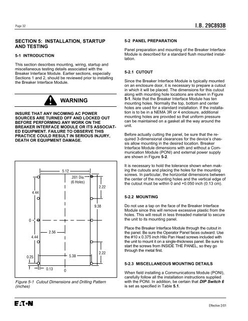
Figure 5-1 Cutout Dimensions and Drilling Pattern<br />
(inches)<br />
0<br />
5-2 PANEL PREPARATION<br />
I.B. 29C893B<br />
Panel preparation and mounting of the <strong>Breaker</strong> <strong>Interface</strong><br />
<strong>Module</strong> is described for a standard flush mounted installation.<br />
5-2.1 CUTOUT<br />
Since the <strong>Breaker</strong> <strong>Interface</strong> <strong>Module</strong> is typically mounted<br />
on an enclosure door, it is necessary to prepare a cutout<br />
in which it will be placed. The dimensions for this cutout<br />
along with mounting hole locations are shown in Figure<br />
5-1. Note that the <strong>Breaker</strong> <strong>Interface</strong> <strong>Module</strong> has ten<br />
mounting holes. Normally the top, bottom and center<br />
holes are used for a standard installation. If the installation<br />
is to be in a NEMA 3R or 4 enclosure, additional<br />
mounting holes are provided so that uniform pressure<br />
can be maintained on a gasket all the way around the<br />
unit.<br />
Before actually cutting the panel, be sure that the required<br />
3-dimensional clearances for the device’s chassis<br />
allow mounting in the desired location. <strong>Breaker</strong><br />
<strong>Interface</strong> <strong>Module</strong> dimensions with and without a Communication<br />
<strong>Module</strong> (PONI) and external power supply<br />
are shown in Figure 5-2.<br />
It is necessary to hold the tolerance shown when making<br />
the cutouts and placing the holes for the mounting<br />
screws. In particular, the horizontal dimensions between<br />
the center of the mounting holes and the vertical edge of<br />
the cutout must be within 0 and +0.050 inch (0.13 cm).<br />
5-2.2 MOUNTING<br />
Do not use a tap on the face of the <strong>Breaker</strong> <strong>Interface</strong><br />
<strong>Module</strong> since this will remove excessive plastic from the<br />
holes. This will result in less threaded material to secure<br />
the unit to its mounting panel.<br />
Place the <strong>Breaker</strong> <strong>Interface</strong> <strong>Module</strong> through the cutout in<br />
the panel. Be sure the Operator Panel faces outward. Use<br />
the #10 x 0.375 inch Hilo Pan Head screws included with<br />
the unit to mount it on a single-thickness panel. Be sure to<br />
start the screws from INSIDE THE PANEL, so they go<br />
through the metal first.<br />
5-2.3 MISCELLANEOUS MOUNTING DETAILS<br />
When field installing a Communications <strong>Module</strong> (PONI),<br />
carefully follow all the installation instructions supplied<br />
with the PONI. In addition, be certain that DIP Switch 6<br />
is set as specified in Table 5.1.<br />
Effective 2/01


