

Breaker Interface Module II - Eaton Canada
Breaker Interface Module II - Eaton Canada
Breaker Interface Module II - Eaton Canada

Create successful ePaper yourself
Turn your PDF publications into a flip-book with our unique Google optimized e-Paper software.
Page 30<br />
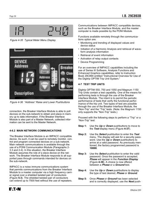
Figure 4-35 Typical Meter Menu Display<br />
Figure 4-36 “Address” Raise and Lower Pushbuttons<br />
connection, the <strong>Breaker</strong> <strong>Interface</strong> <strong>Module</strong> is able to poll<br />
devices on the sub-network to obtain and place in memory<br />
up to date information. If the <strong>Breaker</strong> <strong>Interface</strong><br />
<strong>Module</strong> is also part of a Master Network, collected information<br />
can be sent to the Master Network.<br />
4-6.2 MAIN NETWORK COMMUNICATIONS<br />
The <strong>Breaker</strong> <strong>Interface</strong> <strong>Module</strong> is an IMPACC compatible<br />
device. As such, it can be used to remotely monitor, control<br />
and program connected devices on a sub-network.<br />
Main network communications is available through the<br />
use of a PONI Communication <strong>Module</strong> (Paragraphs 2-<br />
3.3 and 2-4). In this situation, the <strong>Breaker</strong> <strong>Interface</strong><br />
<strong>Module</strong> assumes the role of a slave device on the network.<br />
The <strong>Breaker</strong> <strong>Interface</strong> <strong>Module</strong> responds to all supported<br />
pass through commands intended for devices on<br />
the sub-network.<br />
IMPACC is a noise immune communications system<br />
that permits communications from the <strong>Breaker</strong> <strong>Interface</strong><br />
<strong>Module</strong> to a master computer via a high frequency carrier<br />
signal over a shielded twisted pair of conductors<br />
(Figure 5-3). The shielded twisted pair of conductors<br />
can extend up to 7500 feet without the use of repeaters.<br />
I.B. 29C893B<br />
Communications between IMPACC compatible devices,<br />
such as the <strong>Breaker</strong> <strong>Interface</strong> <strong>Module</strong>, and the master<br />
computer is made possible by the PONI <strong>Module</strong>.<br />
Functions available remotely through the communications<br />
option are:<br />
• Monitoring and trending of displayed values and<br />
device status<br />
• Initiation of a Harmonic Analysis and retrieval of waveform<br />
analysis information<br />
• Retrieval of event information<br />
• Activation of relay output contacts<br />
• Device Programming<br />
For an overview of IMPACC capabilities including the<br />
use of Series <strong>II</strong>I Software, Analysis Functions and<br />
Enhanced Graphics capabilities, refer to Instruction<br />
Book 29C890 entitled “Instructional Overview for Use of<br />
the Digitrip OPTIM Trip Unit System.”<br />
4-7 TEST TRIP UNITS<br />
Digitrip OPTIM 550, 750 and 1050 and Magnum 1150<br />
Trip Units contain a test capability. One of the means for<br />
performing tests is through the use of the <strong>Breaker</strong><br />
<strong>Interface</strong> <strong>Module</strong>. The intent is to permit the periodic<br />
performance of tests that verify the functional performance<br />
of the trip unit. Two types of test are possible<br />
through the use of the <strong>Breaker</strong> <strong>Interface</strong> <strong>Module</strong>, the<br />
“Non-Trip” and the “Trip” tests. (Note: the Magnum 1150<br />
only supports the “Non-Trip” tests.)<br />
Proceed with the following steps to perform a “Trip” or a<br />
“Non-Trip” test:<br />
Step 1: Use the Up or Down pushbuttons to move to<br />
the Test display menu (Figure 4-37).<br />
Step 2: Use the Select pushbutton to enter the Test<br />
menu. The display will ask for a security password.<br />
Use the Up or Down pushbuttons to<br />
arrive at a valid password. As previously mentioned,<br />
the factory programmed password is<br />
10000.<br />
Step 3: Use the Select pushbutton to enter the valid<br />
password. Once the password is accepted,<br />
Phase will appear in the Function Display<br />
(Figure 4-38). A choice is now offered<br />
between a Phase or a Ground test.<br />
Step 4: Use the Up or Down pushbuttons to display<br />
the type of test desired, Phase or Ground.<br />
Step 5: Once Phase or Ground has been selected<br />
and is correctly displayed, use the Next push-<br />
Effective 2/01


