

Breaker Interface Module II - Eaton Canada
Breaker Interface Module II - Eaton Canada
Breaker Interface Module II - Eaton Canada

Create successful ePaper yourself
Turn your PDF publications into a flip-book with our unique Google optimized e-Paper software.
Page 6<br />
In the down position, the <strong>Breaker</strong> <strong>Interface</strong> <strong>Module</strong> will<br />
search through the network for connected devices, learn<br />
their addresses/ descriptions, and store the information in<br />
non-volatile memory. Once the learning or updating<br />
processes have been completed, DIP switch 1 should be<br />
moved to the “Run” (up) position.<br />
Switches 2, 3, 4 and 5: These switches are not used.<br />
They are intended for possible future enhancements<br />
and must be in the down position.<br />
! CAUTION<br />
ONLY CONNECT OR DISCONNECT A COMMUNICA-<br />
TIONS MODULE (PONI) WITH DIP SWITCH 6 IN THE<br />
“OFF” (DOWN) POSITION. FAILURE TO DO SO CAN<br />
CAUSE PERMANENT DAMAGE TO THE PONI.<br />
Switch 6: This switch is referred to as a PONI power<br />
switch. The switch is in the “On” (up) position only when<br />
a communication module (PONI) is being used for network<br />
communications via IMPACC. It is in the “Off”<br />
(down) position when the <strong>Breaker</strong> <strong>Interface</strong> <strong>Module</strong> is<br />
communicating on a sub-network only, or when a PONI<br />
is being connected or disconnected.<br />
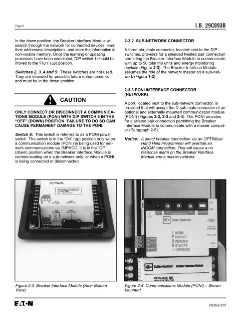
Figure 2-3 <strong>Breaker</strong> <strong>Interface</strong> <strong>Module</strong> (Rear Bottom<br />
View)<br />
2-3.2 SUB-NETWORK CONNECTOR<br />
I.B. 29C893B<br />
A three pin, male connector, located next to the DIP<br />
switches, provides for a shielded twisted pair connection<br />
permitting the <strong>Breaker</strong> <strong>Interface</strong> <strong>Module</strong> to communicate<br />
with up to 50 total trip units and energy monitoring<br />
devices (Figure 2-3). The <strong>Breaker</strong> <strong>Interface</strong> <strong>Module</strong><br />
assumes the role of the network master on a sub-network<br />
(Figure 1-2).<br />
2-3.3 PONI INTERFACE CONNECTOR<br />
(NETWORK)<br />
A port, located next to the sub-network connector, is<br />
provided that will accept the D-sub male connector of an<br />
optional and externally mounted communication module<br />
(PONI) (Figures 2-2, 2-3 and 2-4). The PONI provides<br />
for a twisted pair connection permitting the <strong>Breaker</strong><br />
<strong>Interface</strong> <strong>Module</strong> to communicate with a master computer<br />
(Paragraph 2-5).<br />
Notice: A direct breaker connection via an OPTIMizer<br />
Hand Held Programmer will override an<br />
INCOM connection. This will cause a no<br />
response alarm on the <strong>Breaker</strong> <strong>Interface</strong><br />
<strong>Module</strong> and a master network.<br />
Figure 2-4 Communications <strong>Module</strong> (PONI) – Shown<br />
Mounted<br />
Effective 2/01


